
Powered rolling pry bar for repositioning heavy loads

a technology of heavy loads and powered rolling, which is applied in the direction of crowbars, lifting devices, etc., can solve the problems of increased burden on the human operator, excessive maneuvering space, and high rates of musculoskeletal injuries, and achieve the effect of increasing the traction of motor-driven wheels

Pending Publication Date: 2019-09-12
GOVERNMENT OF THE UNITED STATES AS REPRESENTED BY THE SEC OF THE AIR FORCE
View PDF2 Cites 0 Cited by
  • Summary
  • Abstract
  • Description
  • Claims
  • Application Information

AI Technical Summary

Benefits of technology

The present patent provides an apparatus and system to reposition heavy loads using a powered rolling element. The apparatus includes a tongue and a longer handle or foot plate to provide leverage and increase the downward force on the rolling element. The increased pressure on the rolling element helps generate effective horizontal motion and force. The apparatus can be rapidly reoriented to different loads. Overall, the technical effect of the patent is to provide a better and more efficient way to move heavy loads horizontally.

Problems solved by technology

Over time, the strain of repositioning such loads results in high rates of musculoskeletal injuries.
While movement aids such roller bearing strips in the floor of the cargo vehicle or loads that are on wheels may reduce the force required to reposition a load, they do not eliminate the burden entirely.
In addition, in actual harsh field conditions, these bearings or wheels may not operate as efficiently as intended, placing greater burden on the human operator.
Some aircraft are equipped with winches and cabling to assist the human operator placing the load into an aircraft, but such devices are understood to be underutilized because they are inconvenient, require extensive safety checks, or simply lack the ability to maneuver loads to the particular desired position.
Other means such as well-known pallet movers may not be available, may require excessive maneuver space, may damage the floor of a conveyance, or may not be able to manipulate a pallet without holes to accept the forks of the pallet mover.

Method used


Image

  • Powered rolling pry bar for repositioning heavy loads
  • Powered rolling pry bar for repositioning heavy loads
  • Powered rolling pry bar for repositioning heavy loads

Examples


Embodiment Construction

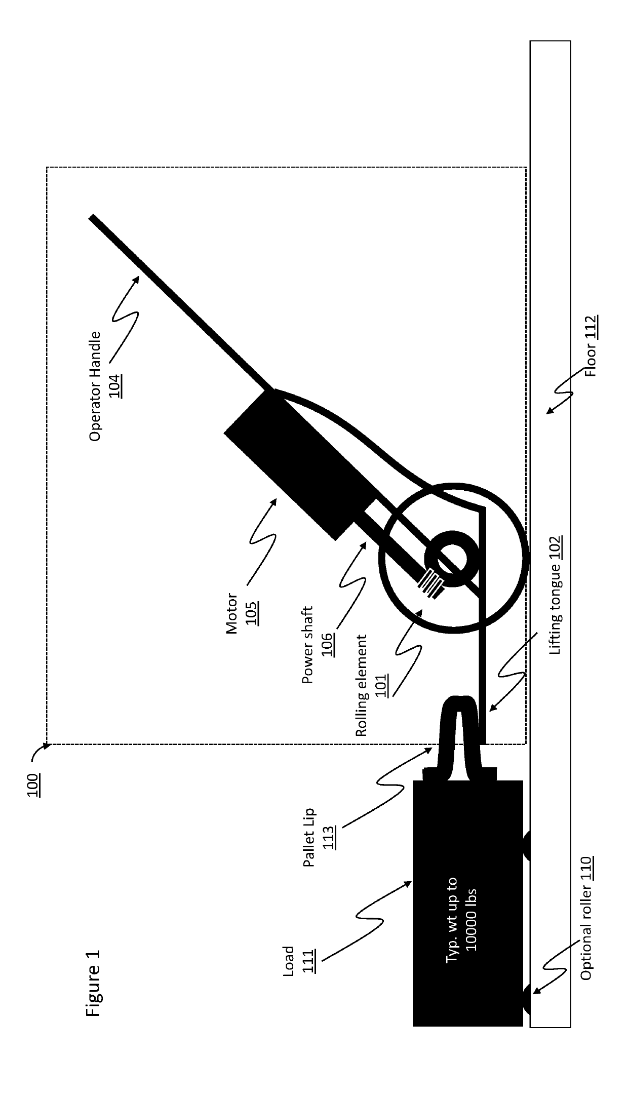
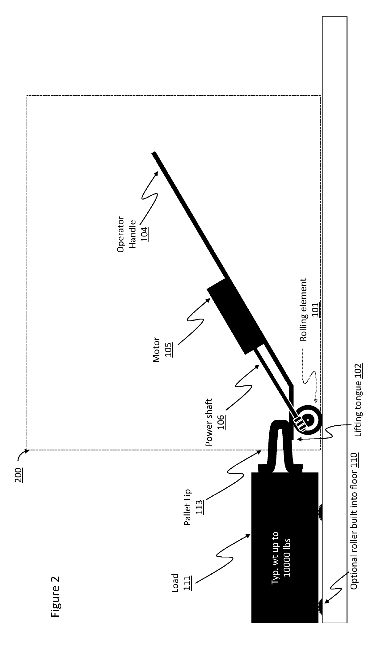
[0024]The various methods, systems, apparatus, and devices described herein generally provide for improved ability to reposition heavy loads. Embodiments of the present invention are directed to a powered device that leverages the weight of the object to be moved to create sufficient downward force to permit application of horizontal force sufficient to push or pull the load to be repositioned.

[0025]While this invention is amenable to being embodied in many different forms, there is shown in the drawings and will herein be described in detail specific embodiments, with the understanding that the present disclosure is to be considered as an example of the principles of the invention and not intended to limit the invention to the specific embodiments shown and described. In the description below, like reference numerals may be used to describe the same, similar or corresponding parts in the several views of the drawings.

[0026]Referring now to the drawings, FIG. 1 is a depiction of an ...


PUM


Abstract

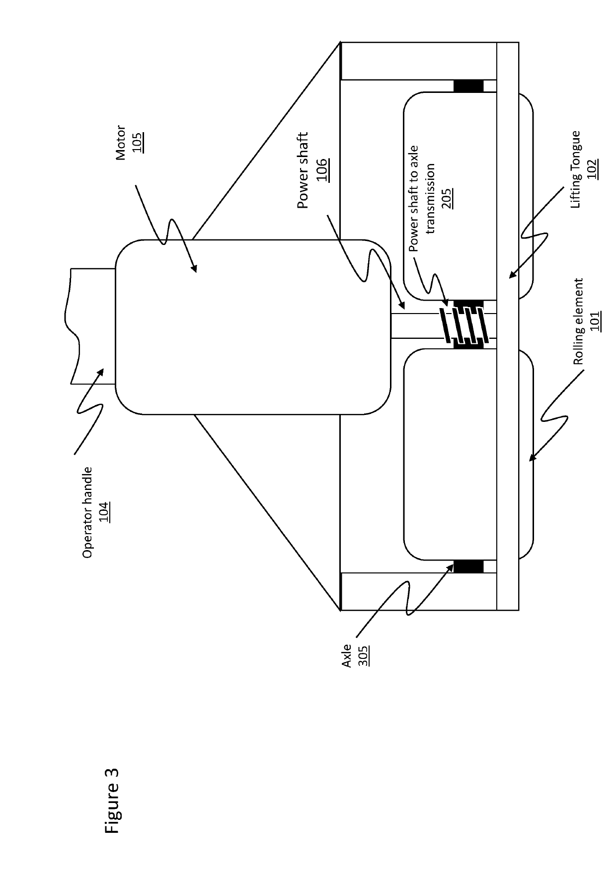
An apparatus and system for repositioning heavy loads. Apparatus features an operator handle capable of positioning a lifting tongue under a load to be repositioned. The apparatus further features a set of motor driven wheels that engage the floor or other surface with the aid of friction or other traction means to propel the load forward or backward. Downward pressure on the operator handle while the lifting tongue is positioned under the load increase the motor driven wheels traction. The system further features rolling elements integral to the floor to further aid repositioning of the load as well as mechanical engagement means between the motor driven wheels and the floor where adequate friction between the same is not possible. The apparatus further features an addition set of unpowered wheels that may be alternately repositioned for engagement with the floor so as to lift the motor driven wheels out of contact with the floor to aid in orienting the apparatus with the load.

Description

CROSS REFERENCE TO RELATED APPLICATIONS[0001]This application claims the benefit under 35 U.S.C. § 119(e) of U.S. Provisional Patent Application Ser. No. 62 / 640,256 filed on Mar. 8, 2018 the entire content of which is incorporated herein by reference.STATEMENT OF GOVERNMENT INTEREST[0002]The invention described herein may be manufactured, used and licensed by or for the Government of the United States for all governmental purposes without the payment of any royalty.FIELD OF THE INVENTION[0003]The present disclosure relates generally to an apparatus to assist human operators in repositioning heavy loads, such as pallets, without lifting them.BACKGROUND OF THE INVENTION[0004]Cargo movers such as airmen positioning pallets of material on cargo airplanes, often must reposition heavy loads without the assistance of vehicles or other heavy machinery. Over time, the strain of repositioning such loads results in high rates of musculoskeletal injuries. While movement aids such roller bearing...

Claims


Application Information

Patent Timeline
IPC IPC(8): B66F9/065B66F15/00
CPCB66F15/00B66F9/065
Inventor LINDERMAN, MARK HERRON
Owner GOVERNMENT OF THE UNITED STATES AS REPRESENTED BY THE SEC OF THE AIR FORCE
Learn More