
Media processing device

a technology of a processing device and a media, applied in the direction of thin material processing, article separation, function indicators, etc., can solve the problem of slack produced by the difference in roller speed, and achieve the effect of not increasing the nip pressure of the transportation roller

Inactive Publication Date: 2011-03-08
SEIKO EPSON CORP
View PDF15 Cites 4 Cited by
  • Summary
  • Abstract
  • Description
  • Claims
  • Application Information

AI Technical Summary

Benefits of technology

[0011]A media processing device according to the present invention can convey sheet media at a constant speed of transportation passed an information scanning position without increasing the nip pressure of the transportation roller.
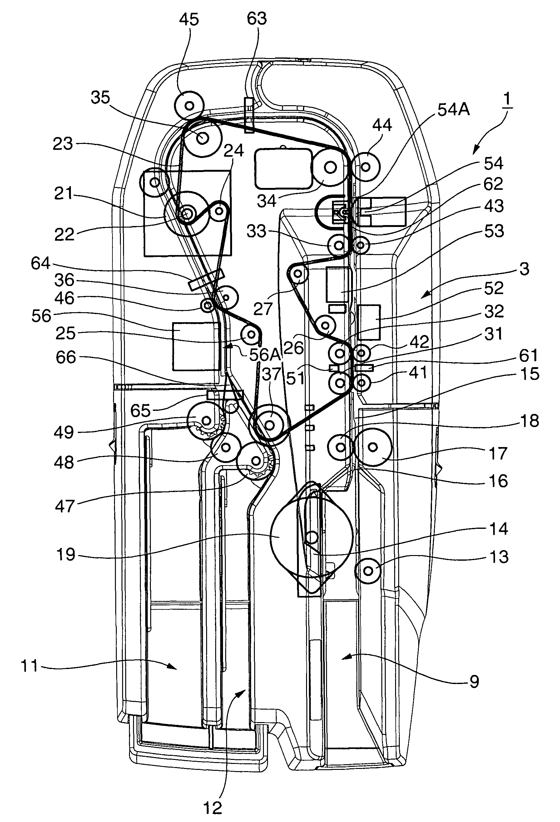
[0013]With the media processing device according to the invention sheet media delivered from the separation mechanism are fed first to the first transportation roller that turns at a fast media transportation speed, and then from there to the second transportation roller. The feed speed of the first transportation roller is set to be faster than the speed of the second transportation roller even if there is some slipping between the first transportation roller and the sheet medium. The sheet medium advanced to the second transportation roller is thus conveyed at a slower speed than the transportation speed of the first transportation roller to the information reading position. As a result, slack is produced by this difference in roller speed in the part of the sheet media that is between the first transportation roller and the second transportation roller. This slack prevents the effect of resistance and transportation load imposed by the separation mechanism from being passed from the first transportation roller to the second transportation roller. More specifically, the transportation resistance produced by the separation mechanism acts on the first transportation roller but does not act on the second transportation roller. Variation in the load on the second transportation roller is therefore suppressed, and the sheet media can be conveyed passed the information reading position at a constant speed while the information reader scans the media without the second transportation roller slipping against the medium.
[0014]Preferably, the difference between the peripheral velocity of the first transportation roller and second transportation roller is approximately 2% to 3%. This difference prevents any effect on the second transportation roller even if the first transportation roller slips against the sheet medium.
[0016]If the outside diameter of the first transportation roller and the second transportation roller are the same, the same effect can be achieved by driving the first transportation roller at a faster angular velocity than the angular velocity of the second transportation roller.
[0021]The invention therefore prevents the transportation load imposed by the separation mechanism from acting on the second transportation roller that feeds the sheet media to the information reading position. The transportation load on the second transportation roller can therefore be reduced and variation in the transportation load can be suppressed. The transportation speed is thus constant, and slipping between the second transportation roller and the sheet media can be minimized.
[0022]The invention can thus improve the relay capacity of the second transportation roller, convey the sheet media at a constant speed passed the information reading position, and prevent a drop in the reading accuracy of the information reader.

Problems solved by technology

As a result, slack is produced by this difference in roller speed in the part of the sheet media that is between the first transportation roller and the second transportation roller.

Method used


Image

  • Media processing device
  • Media processing device
  • Media processing device

Examples


Embodiment Construction

[0032]A preferred embodiment of a check processing device according to the present invention is described below with reference to the accompanying figures.

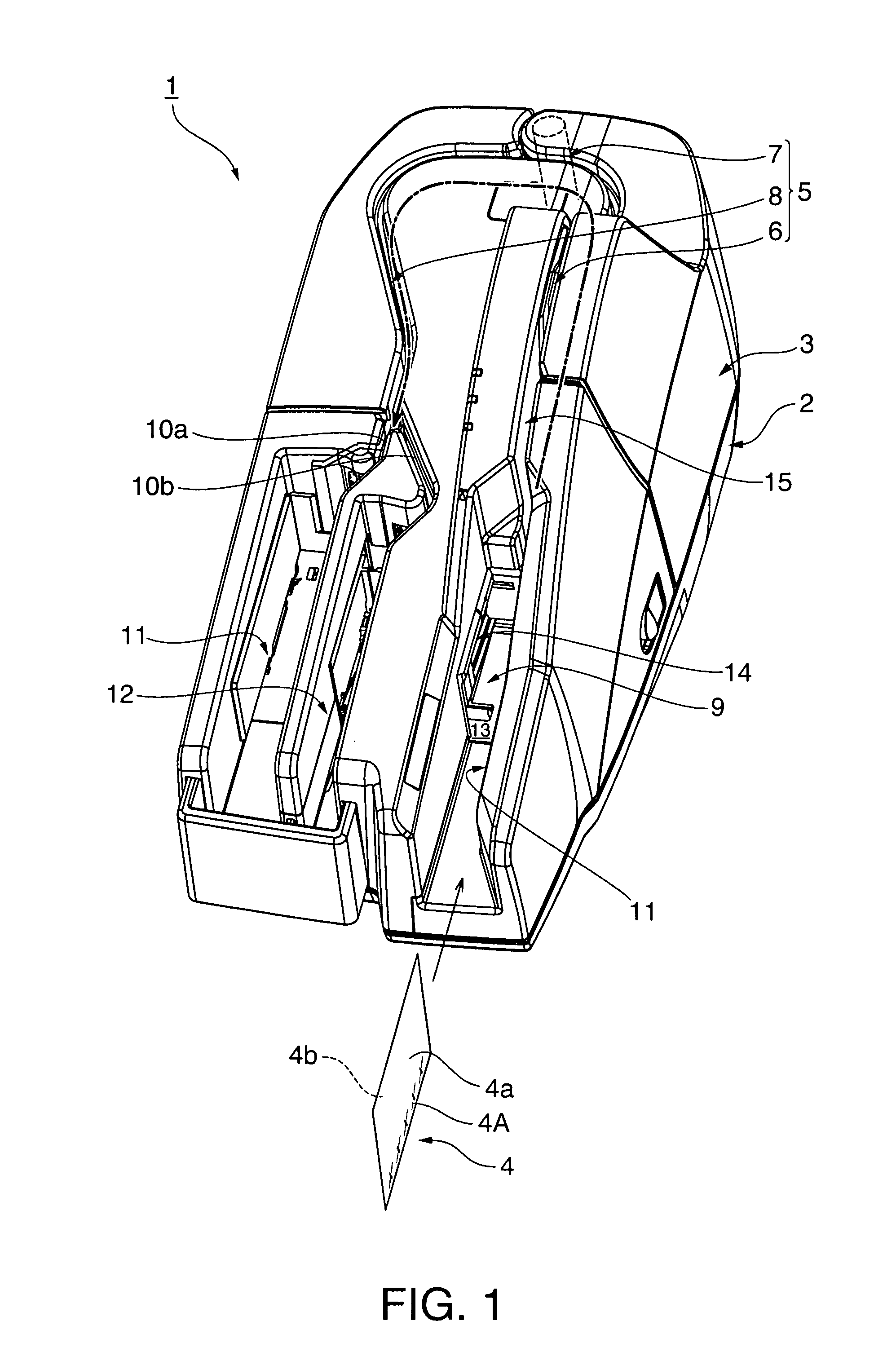
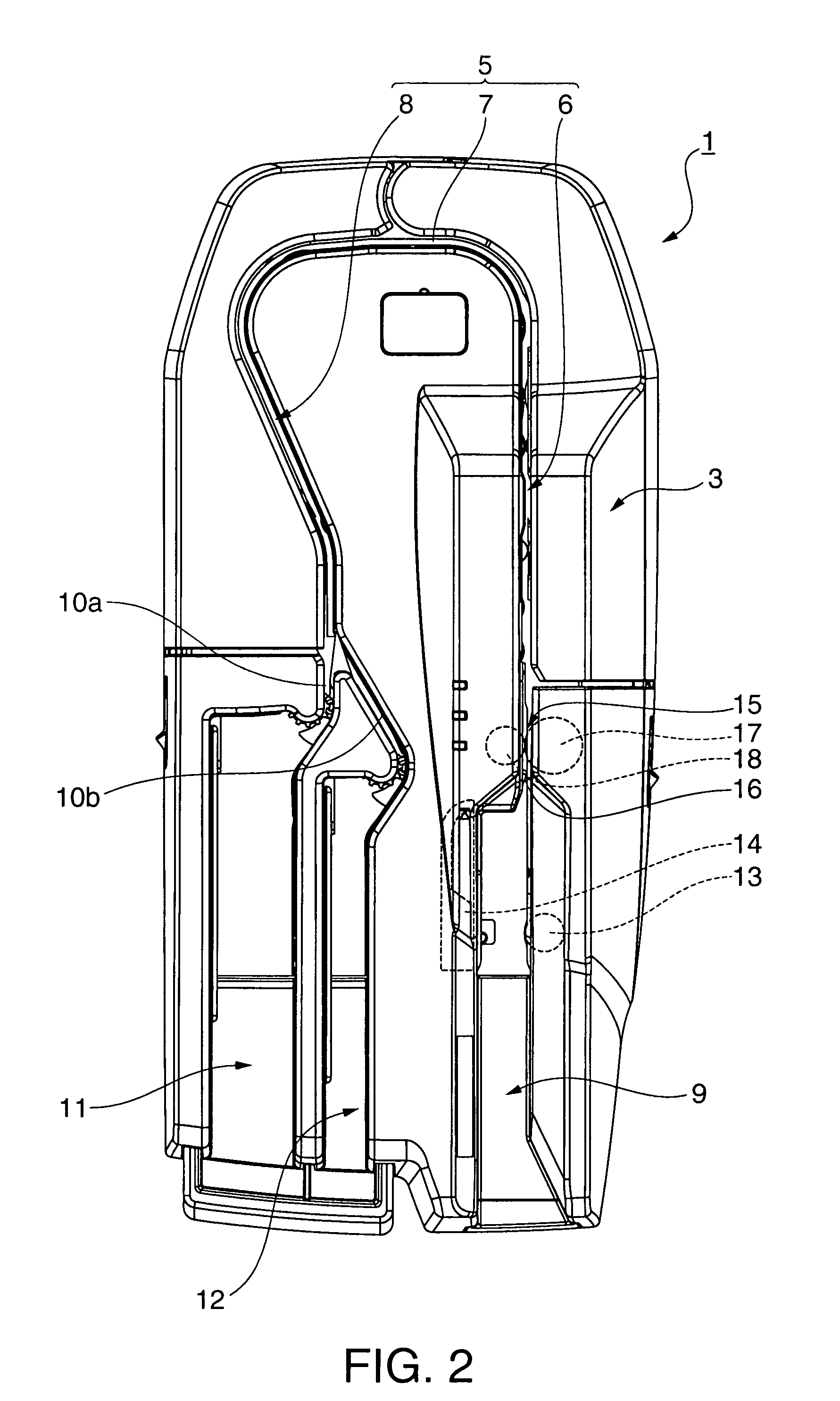
[0033]FIG. 1 is an external oblique view of a check processing device 1 according to the invention, and FIG. 2 is a plan view of the same.

[0034]This check processing device 1 has a case 2 and a rear case 3 that covers the top of the case 2, and various parts and assemblies are disposed inside the case. A transportation path 5 for conveying checks 4 (sheet media) is formed in the rear case 3.

[0035]The check transportation path 5 is a narrow vertical slot that curves in a basically U-shaped configuration when seen from above, and includes a straight upstream-side transportation path portion 6, a curved transportation path portion 7 that continues from the upstream-side transportation path portion 6, and a slightly curving downstream-side transportation path portion 8 that continues from the curved transportation path portion 7.

[0036...


PUM

PropertyMeasurementUnit
speedaaaaaaaaaa
velocityaaaaaaaaaa
angular velocityaaaaaaaaaa

Abstract

A media processing device can convey checks at a constant speed passed an information reading position without slipping and without increasing the relay capacity of the transportation roller. The check processing device 1 has two transportation rollers 31 and 32 between the scanning position 52A of the contact image scanner 52 and the separation roller 17 and retard roller 18 that produce a transportation load or transportation load variation. The upstream-side transportation roller 31 turns faster than the downstream transportation roller 32 so that the checks 4 are fed with slack between these transportation rollers 31 and 32. Because of this slack in the part 402 of the check 4 between the transportation rollers 31 and 32, the transportation load from the separation mechanism does not act on the downstream transportation roller 32. The transportation load acting on the transportation roller 32 that feeds the checks 4 to the scanning position 52A can thus be reduced, variation in the transportation load can be suppressed, checks can be conveyed at a constant speed to the scanning position 52A, and a drop in the reading accuracy of the contact image scanner 52 can be prevented.

Description

BACKGROUND OF THE INVENTION[0001]1. Field of Invention[0002]The present invention relates to a media processing device that reads contained information such as magnetic ink characters and image information from sheet media such as checks while conveying the media one at a time through a transportation path, and relates more particularly to a media processing device that can suppress fluctuations in the sheet media transportation speed so that the contained information can be accurately scanned.[0003]2. Description of Related Art[0004]Banks and other financial institutions use check readers to image and read magnetic ink characters from checks, promissory notes, and other check-like negotiable instruments, and to sort the checks based on the acquired information. As electronic check processing has become more common in recent years the scanned image data and magnetic ink character data is also processed and managed using computers. See, for example, the check readers taught in Japane...

Claims


Application Information

Patent Timeline
Patent Type & Authority Patents(United States)
IPC IPC(8): B65H5/22
CPCB65H5/062B65H2301/3122B65H2301/321B65H2301/51512B65H2404/143B65H2513/104B65H2701/1912B65H2801/39B65H2220/09B65H2220/02B65H2220/11B65H2513/10
Inventor FURIHATA, HIDEKISASAKI, TOSHIYUKI
Owner SEIKO EPSON CORP
Learn More