Laterally adjustable optical mount with bent lever manipulator units

a technology of manipulator units and optical mounts, applied in the field of monolithic optical mounts, can solve the problems of increased production costs, system instability, complex and unsymmetrical structure, etc., and achieve the effects of high lateral and axial stiffness, high tension, and high sensitive adjustment of optical elements

a technology of manipulator units and optical mounts, applied in the field of monolithic optical mounts, can solve the problems of increased production costs, system instability, complex and unsymmetrical structure, etc., and achieve the effects of high lateral and axial stiffness, high tension, and high sensitive adjustment of optical elements

US7903353B2Active Publication Date: 2011-03-08JENOPTIK OPTICAL SYST

Image

  • Laterally adjustable optical mount with bent lever manipulator units
  • Laterally adjustable optical mount with bent lever manipulator units
  • Laterally adjustable optical mount with bent lever manipulator units

Examples


first embodiment

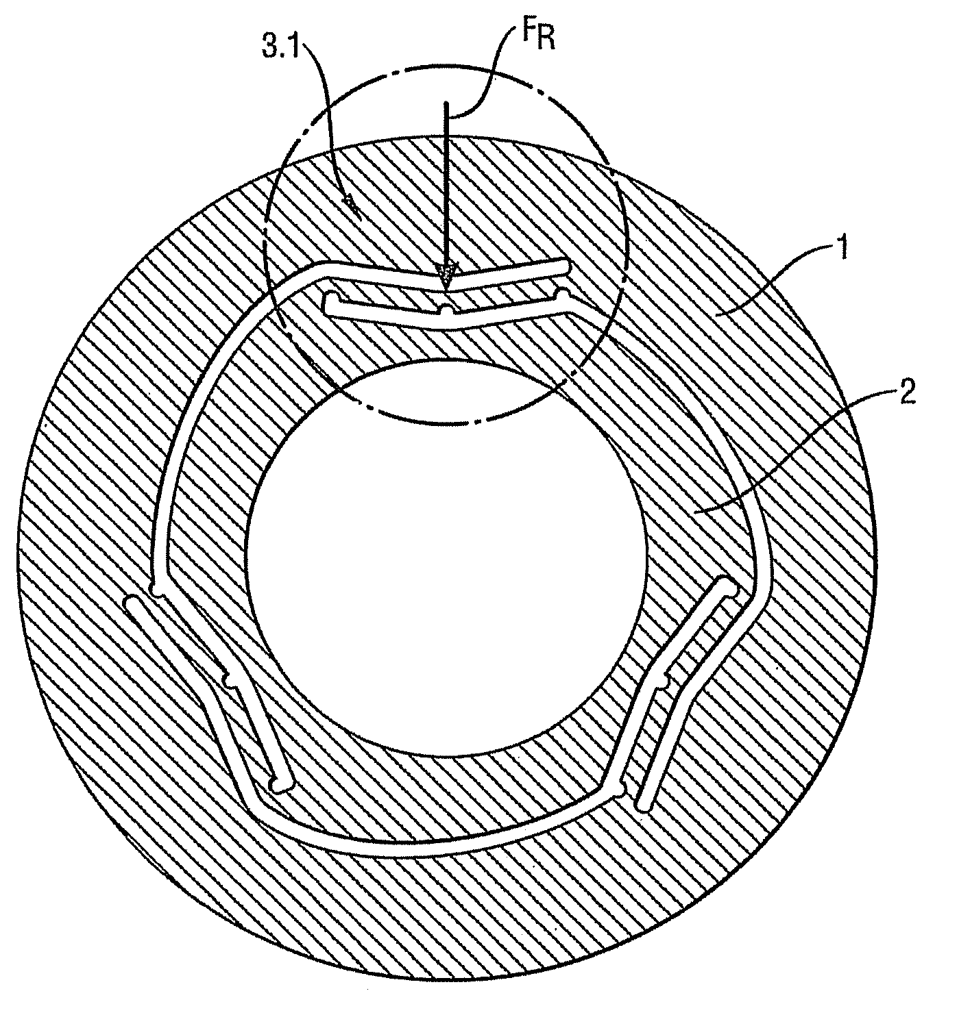
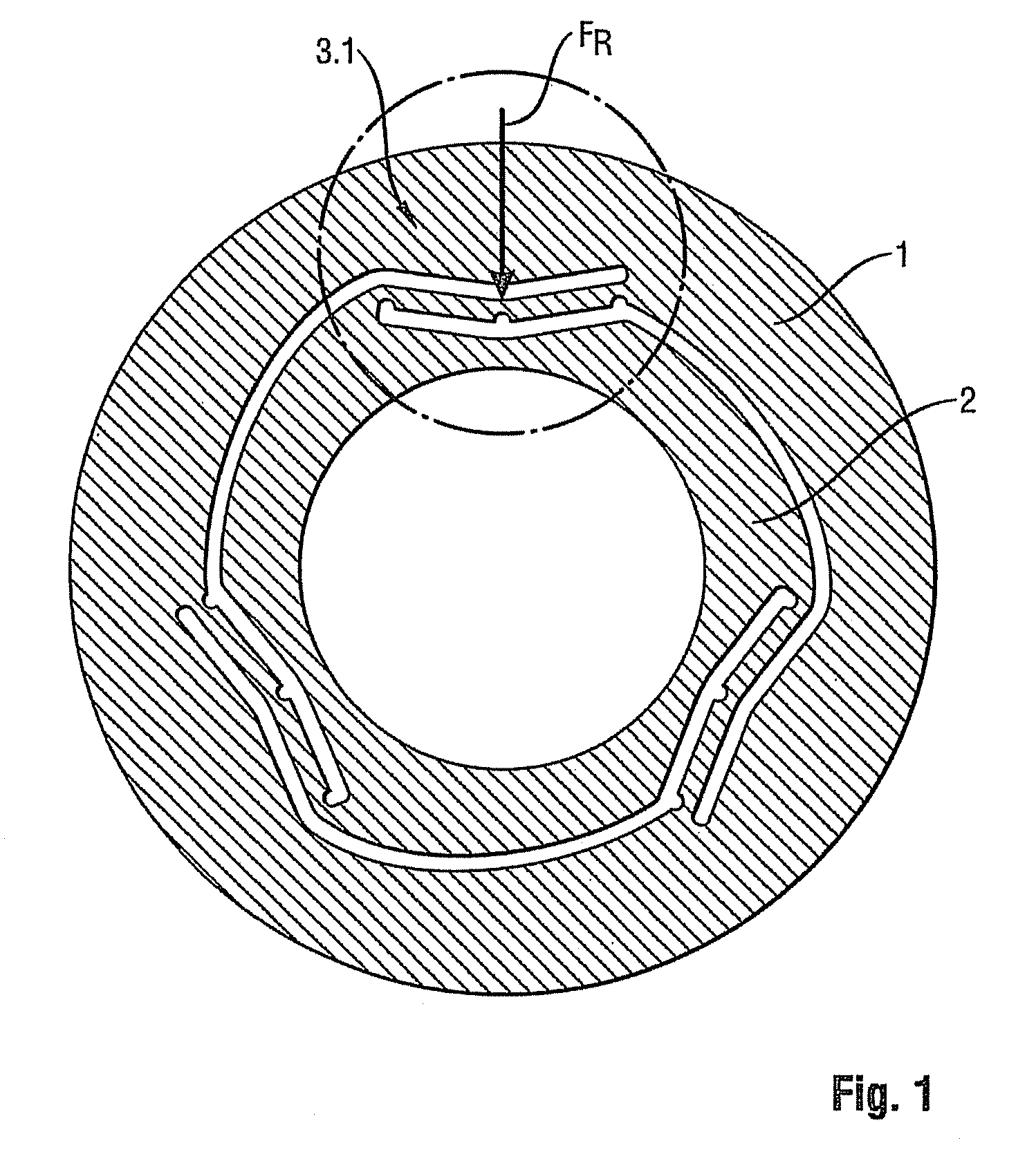
[0030]FIG. 1 shows a lens mount with a bent lever manipulator unit 3.1.

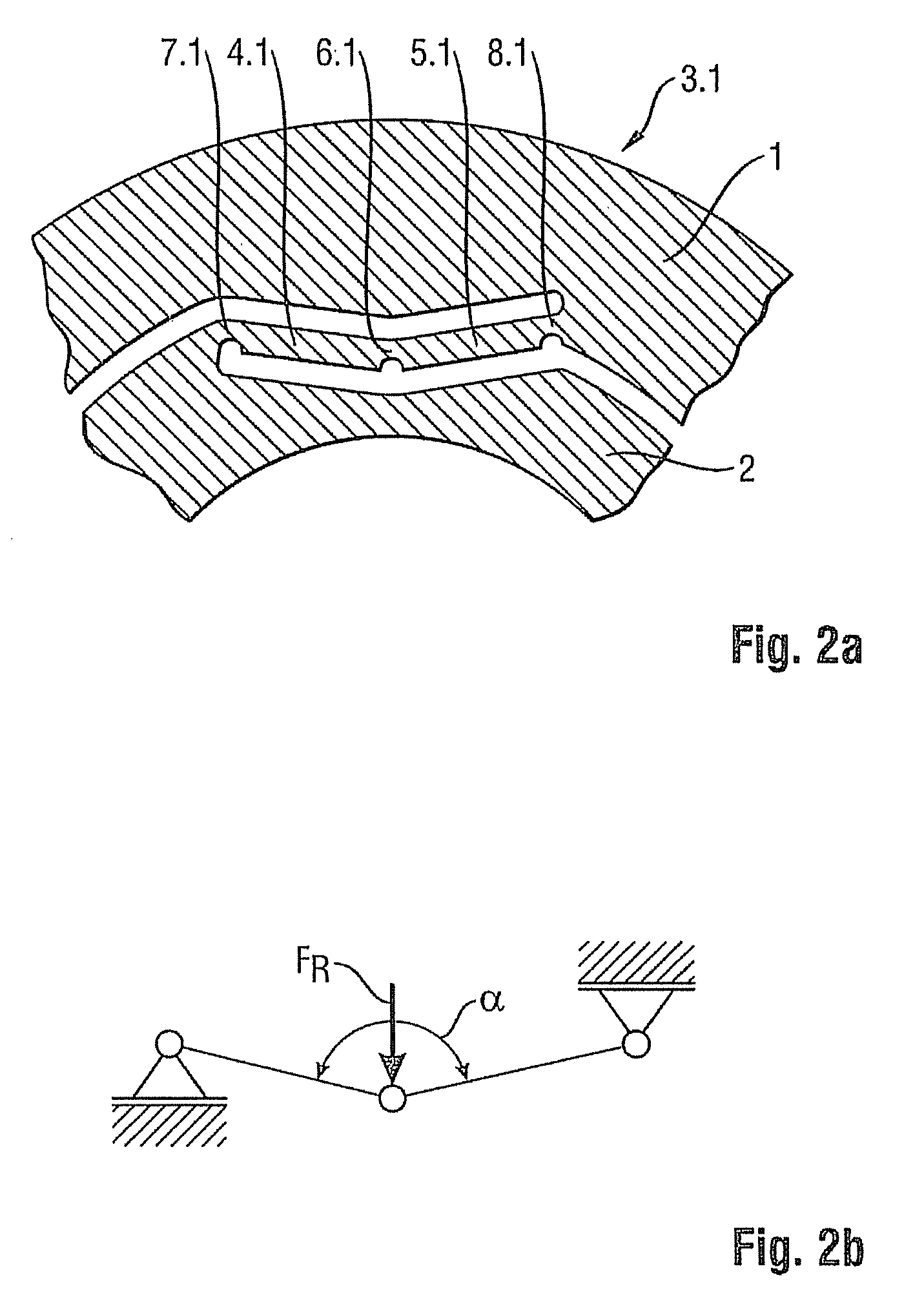
[0031]FIGS. 2a, 3a and 4a show sectional views of different embodiments of bent lever manipulator units 3.1, 3.2, 3.3 to better illustrate the different orientations of the cuts in the material.

[0032]FIGS. 2b, 3b and 4b show the force diagrams associated with these units.

[0033]A first embodiment of a bent lever manipulator unit 3.1 which is shown in FIGS. 1, 2a and 2b comprises a bent lever with a first element 4.1 which is connected to a second element 5.1 by way of a bent lever flexure hinge 6.1.

[0034]Within the adjustable range of the bent lever, the first element 4.1 and the second element 5.1, in any position, form a bent angle α smaller than 180°, which angle changes with the adjustable movement, with bent angle α in the context of the present invention always identifying the smaller angle between the first elements 4.1 and the second elements 5.1.

[0035]The other end of the first element 4.1 is connected to...

third embodiment

[0042]In a bent lever manipulator unit 3.3, the connection to the outer mounting ring 1 is not tapered and is therefore not a mechanical element in the sense of a flexure hinge, but is instead a fixed constraint 10.3 for the additional lever 9.3 which is rigidly connected to a second element 5.3.

[0043]The design of a first flexure hinge 7.3, of a bent lever flexure hinge 6.3, and of a first element 4.3, which are comprised in the third embodiment of a bent lever manipulator unit 3.3, is identical to the design of the first flexure hinge 7.2, the bent lever flexure hinge 6.2, and the first element 4.2 of the second embodiment of a bent lever manipulator unit 3.2.

[0044]The mechanisms of action of the three previously explained embodiments of bent lever manipulator units 3 are identical in that each of the bent lever manipulator units 3 when actuated acts as a mechanical element while the other two form a fixed support.

[0045]If, on each first flexure hinge 7 of the fixed supports, one ...


PUM


Abstract

The present invention relates to an optical mount, in particular a lens mount, which is divided by a plurality of cuts in the mount material into a stationary outer mounting ring, a laterally adjustable inner mounting ring and three bent lever manipulator units which are offset by 120° relative to one another and which comprise a bent lever having a first element, one end of which is connected by way of a bent lever flexure hinge to one end of a second element, the other end of the first element being connected to the inner mounting ring, the other end of the second element being connected to the outer mounting ring, and with the first and second elements enclosing a bent angle smaller than 180°. By manipulating the three bent lever manipulator units, any center position of the inner mounting ring can be adjusted relative to the center of the outer mounting ring within an intended displacement range.

Description

FIELD OF THE INVENTION[0001]The present invention relates to a monolithic optical mount, in particular a lens mount, which is divided by cuts in the material into a stationary outer mounting ring and a laterally adjustable inner mounting ring. A generic mount is known from EP 1 577 693 A2.BACKGROUND OF THE INVENTION[0002]DE 199 01 295 A1 discloses an optical imaging device in which the outer mount and an inner ring that can be adjusted relative to this outer mount are preferably integrally formed in one piece, i.e., as a monolithic unit. Between the inner ring and the outer mount, a manipulator device for the path-controlled displacement of the optical element, which is mounted in the inner ring in a direction perpendicular to the optical axis consists of a system of peripheral slots with connecting elements located between, a swivel joint and at least one adjustable joint with an adjusting element.[0003]The drawback of this solution is that, in particular, because of the plurality ...

Claims


Application Information

Patent Timeline
08 Mar 2011
Publication
US7903353B2
IPC
G02B7/02
CPC
G02B7/003; G02B7/023
Inventors
REICHMANN, LUTZ; BORNSCHEIN, MARCO