Thermostatic mixing valve

a technology of mixing valve and water pump, which is applied in the direction of valve operating means/release devices, instruments, process and machine control, etc., can solve the problems of reducing ease of operation and life of the valve, and reducing the size of the hot water inlet. , to achieve the effect of increasing the size of the hot water inl

Inactive Publication Date: 2011-03-15
XIAMEN LOTA INT CO LTD
View PDF16 Cites 18 Cited by
  • Summary
  • Abstract
  • Description
  • Claims
  • Application Information

AI Technical Summary

Problems solved by technology

While such conventional mixing valves provide some benefits, including regulated water outlet flow, they nevertheless have certain limitations.
For example, the internal components of conventional mixing valves are susceptible to high levels of friction and premature wear, which reduces ease of operation and the life of the valve.
Also, conventional mixing valves are susceptible to imprecise temperature control of the friction and premature wear, which reduces ease of operation and the life of the valve.
Also, conventional mixing valves are susceptible to imprecise temperature control of the mixed water which is discharged from the fixture to which the mixing valve is operably connected.

Method used


Image

  • Thermostatic mixing valve
  • Thermostatic mixing valve
  • Thermostatic mixing valve

Examples


Embodiment Construction

[0026]While this invention is susceptible of embodiments in many different forms, there is shown in the drawings and will herein be described in detail preferred embodiments of the invention with the understanding that the present disclosure is to be considered as an exemplification of the principles of the invention and is not intended to limit the broad aspect of the invention to the embodiments illustrated.

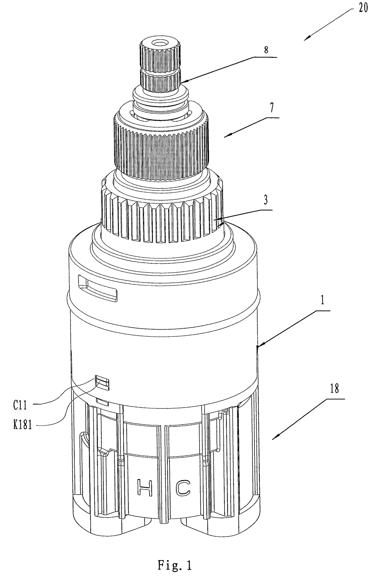
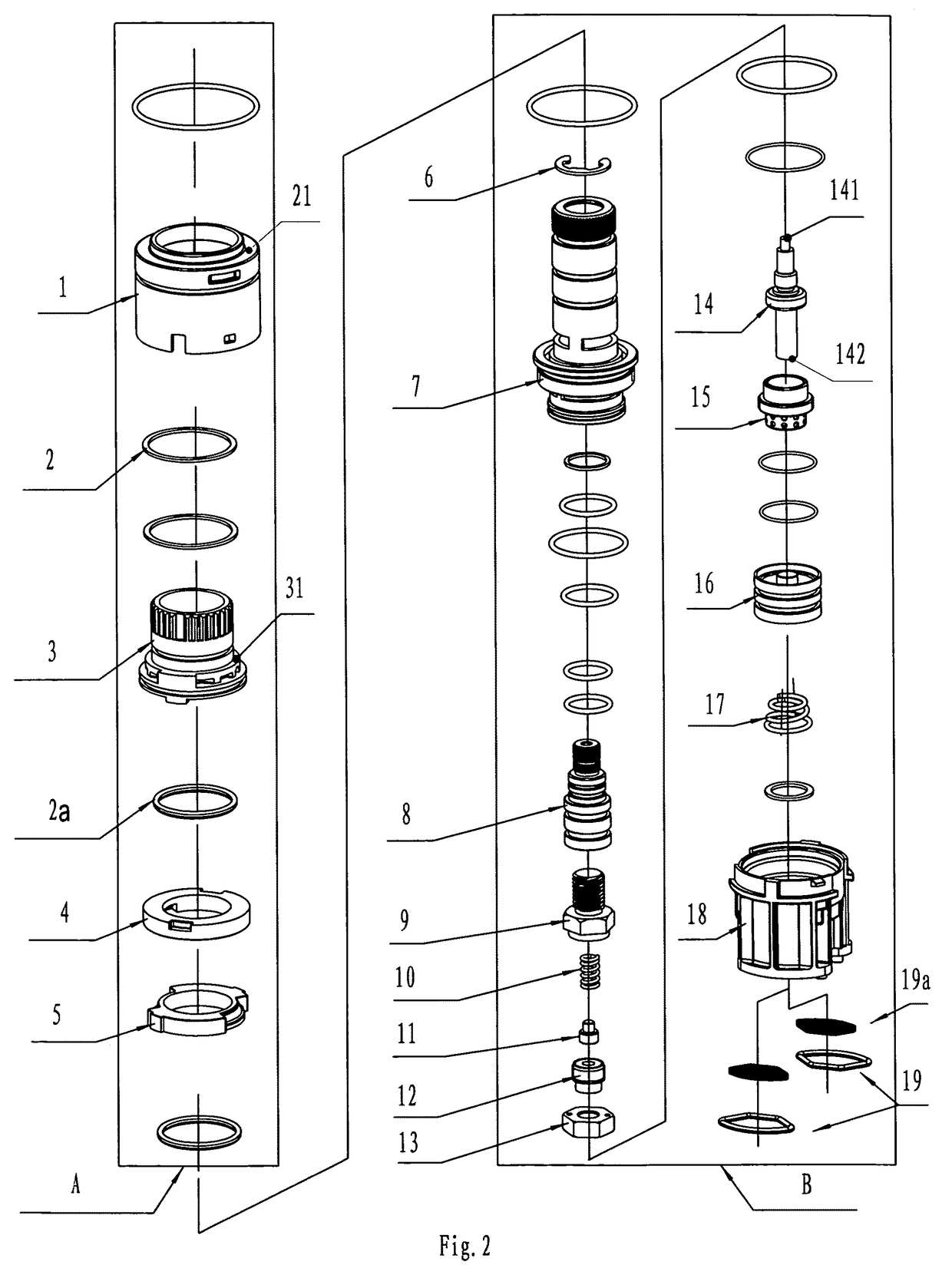
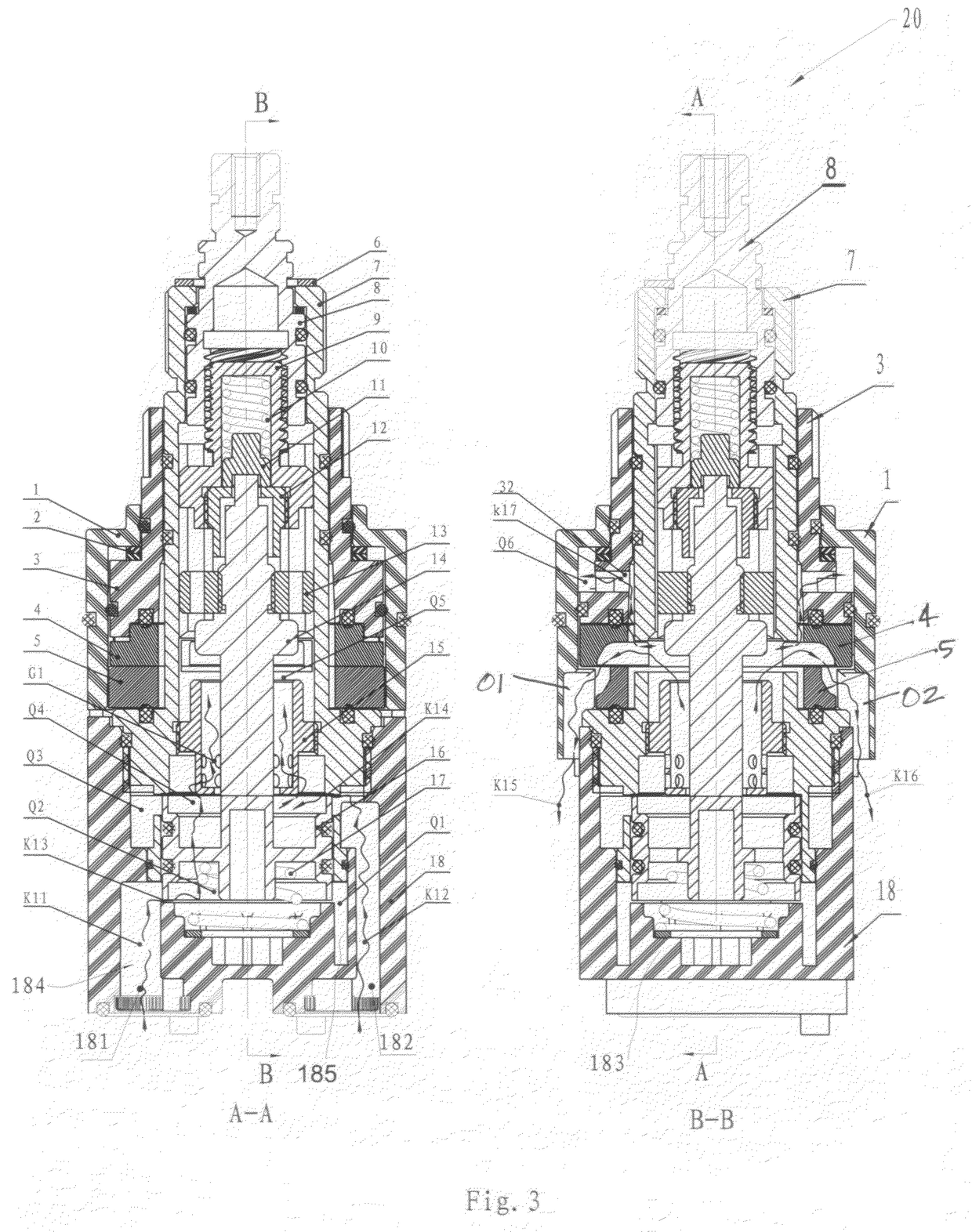
[0027]FIGS. 1-8 show a thermostatic water mixing valve 20 that is installed within a water delivery fixture, such as a faucet or showerhead. As explained in greater detail below, the mixing valve 20 includes a number of internal structures that interact to define a number of flow paths for hot and cold water and at least one outlet flow path. In one embodiment, the mixing valve 20 includes a hot water inlet flow path K11, a cold water inlet flow path K12, a mixer flow path G1, at least one pressure relief flow path K17 and two outlet flow paths K15, K16. These interacting struc...


PUM


Abstract

The invention provides a thermostatic mixing valve for use within a water discharge fixture. The mixing valve comprises a cover defining an interior region, a stationary lower disk residing within the interior region, and a moveable upper disk. The lower and upper disks each have a central opening and at least one peripheral groove, wherein the grooves are alignable to form a peripheral water outlet. The mixing valve also includes a spindle assembly extending through the cover region and operably connected to the upper disk to enable alignment of the grooves and formation of the water outlet. A pressure relief cavity is formed between the spindle assembly and the cover, and wherein water flows through an opening in the spindle assembly and into the relief cavity. In order to reduce friction during operation of the valve, the water in the pressure relief cavity applies downward pressure to the spindle assembly which counter-balances upward pressure applied to the spindle assembly by water flowing through the lower and upper disks. The mixing valve further includes a slide bolt and a mixer, wherein depending upon the selected discharge water temperature, water from the cold and hot water cavities flows through the slide bolt into the mixer for subsequent discharge through the fixture.

Description

CROSS-REFERENCE TO RELATED APPLICATIONS[0001]This application claims priority from British Patent Application No. GB0810938.1, filed on Jun. 13, 2008.FEDERALLY SPONSORED RESEARCH OR DEVELOPMENT[0002]Not applicable.TECHNICAL FIELD[0003]The invention relates to a thermostatic water mixing valve that is installed in a water discharging fixture, such as a faucet or showerhead. The mixing valve includes a number of internal structures that interact to define a hot water flow path, a cold water flow path, two outlet flow paths and at least one relief flow path that enable the mixing valve to discharge a mixed water composition at the volume and temperature selected by the user.BACKGROUND OF THE INVENTION[0004]Thermostatic water mixing valves are well-known, and can be found in both residential and commercial settings. In either setting, the mixing valve combines two water flows, primarily hot and cold water flows, into a stream of mixed temperature water for discharge from the mixing valv...

Claims


Application Information

Patent Timeline
Patent Type & Authority Patents(United States)
IPC IPC(8): G05D23/13
CPCF16K11/0743F16K11/0746F16K31/004G05D23/1353Y10T137/86815F16K11/078
Inventor LI, KEPINGXIONG, JUSHENG
Owner XIAMEN LOTA INT CO LTD
Why Eureka
Try Eureka