Rear vehicle body structure

a rear vehicle and body technology, applied in the direction of roofs, transportation and packaging, vehicle arrangements, etc., can solve the problems of not contributing to the receiving bracket is difficult to disperse the input load to the side sills, etc., to improve the rigidity of the suspension mounting parts, the energy absorption effect at the time of rear end collision can be further enhanced

Inactive Publication Date: 2011-03-15
HONDA MOTOR CO LTD
View PDF16 Cites 36 Cited by
  • Summary
  • Abstract
  • Description
  • Claims
  • Application Information

AI Technical Summary

Benefits of technology

[0010]The present invention has been made in view of the above problem, and an object thereof is to provide a rear vehicle body structure that enables to disperse a load input at the time of rear end collision, and to enhance the rigidity of suspension mounting parts.

Problems solved by technology

Thus, if a load is input to the cross support at the time of rear end collision, the input load is not efficiently transferred from the cross support to the receiving bracket through the support, which causes a problem that it is difficult to disperse the input load to the side sills from the receiving bracket through the compression bars.
Thus, there has been a problem that the receiving bracket does not contribute to the rigidity of the suspension mounting parts for the right and left rear wheels.

Method used


Image

  • Rear vehicle body structure
  • Rear vehicle body structure
  • Rear vehicle body structure

Examples


Embodiment Construction

[0069]A rear vehicle body structure according to an embodiment of the present invention is described in detail below with reference to the accompanying drawings. In the following explanation, terms indicating directions such as “front-rear”, “right-left” and “up-down” are based on directions of a vehicle body to which a cross member is attached, which comprises the rear vehicle body structure.

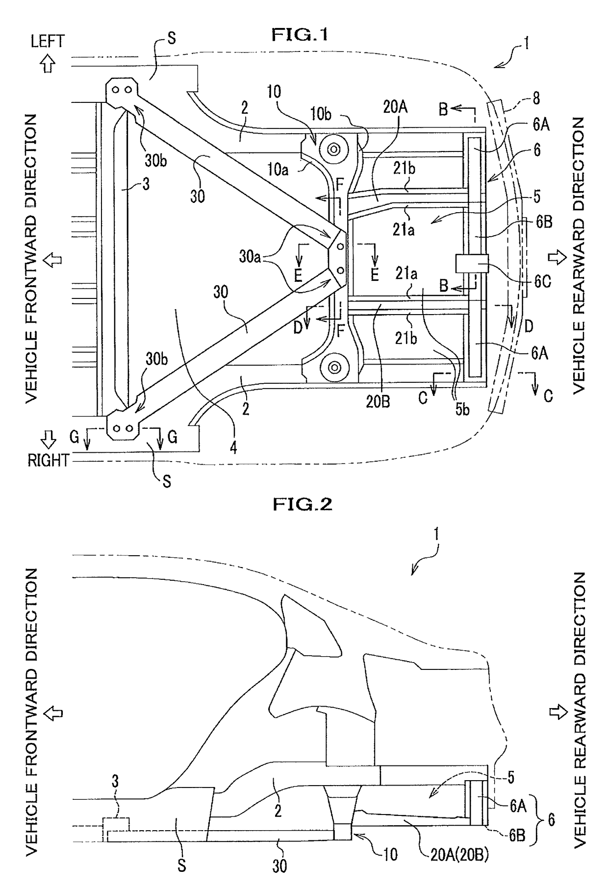
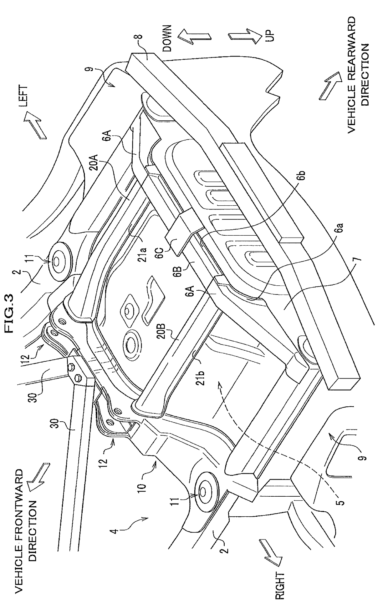
[0070]FIG. 1 is a bottom plain view showing the rear vehicle body structure according to the embodiment of the present invention. FIG. 2 is a side view showing a rear part of a vehicle body including the rear vehicle body structure. FIG. 3 is a perspective view of the rear vehicle body structure seen from the bottom of the structure.

[0071]Firstly, a rear part of a vehicle to which the rear vehicle body structure is applied is briefly explained referring to FIGS. 1 and 2.

[0072]A rear vehicle body of a vehicle 1 includes a pair of right and left rear frames 2, 2 which extend in the front-rear dir...


PUM


Abstract

A rear vehicle body structure including: a cross member which is connected between right and left rear frames extending in the front-rear direction of a vehicle body, the cross member being provided with suspension mounting parts for supporting suspensions of right and left rear wheels; spare pan frames for supporting a spare pan, the spare pan frames being connected to the cross member and extend rearward of the vehicle body from the cross member; and a pair of right and left tank frames which is connected in the vicinity of a center portion of the cross member in the right and left direction of the vehicle body, each of the pair of right and left tank frames extending in the vehicle front-right direction or the vehicle front-left direction from the cross member and being connected to a right or left floor frame or a right or left side sill.

Description

CROSS REFERENCE TO RELATED APPLICATIONS[0001]This application claims the foreign priority benefit under 35 U.S.C. §119 of Japanese Patent Application No. 2006-238422 filed on Sep. 4, 2006, the disclosure of which is incorporated herein by reference.FIELD OF THE INVENTION[0002]The present invention relates to a rear vehicle body structure.DESCRIPTION OF THE RELATED ART[0003]Conventionally, a rear vehicle body structure has been known which is, for example, disclosed in the patent document 1. In the rear vehicle body structure, a rear end of a support which is disposed in the front-rear direction of the vehicle body is connected to a cross support disposed at the rear end of the vehicle body, and a front end of the support is connected to a receiving bracket that is disposed on the front side of the support in the right and left direction of the vehicle body. A pair of compression bars, which extend vehicle frontward in a v shape in a plain view, is further connected to the receiving ...

Claims


Application Information

Patent Timeline
Patent Type & Authority Patents(United States)
IPC IPC(8): B60J7/00
CPCB62D25/087B62D25/2027
Inventor YAMAGUCHI, TOSHIZUMIKAWABE, SATORUTSUYUZAKI, TAKUMI
Owner HONDA MOTOR CO LTD
Why Eureka
Try Eureka