Electrical connector with stress-distribution features

a technology of stress distribution and electric connectors, applied in the direction of printed circuits, electrical devices, etc., can solve the problems of contact deformation and damage to the housing

Active Publication Date: 2011-03-15
FCI AMERICAS TECH LLC
View PDF365 Cites 22 Cited by
  • Summary
  • Abstract
  • Description
  • Claims
  • Application Information

AI Technical Summary

Benefits of technology

[0005]Disclosed herein is an electrical connector that may be capable of inhibiting bowing of the contacts of the connector when the connector is mounted on a substrate. Such a connector may include a housing and a contact mounted in the housing. The contact may include a body, a plurality of terminal pins extending from a first edge of the body and a plurality of contact beams extending from a second edge of the body. At least a portion of the edges of a first contact beam and of a second contact beam may be positioned proximate respective adjacent surfaces of the housing when the connector is not mounted on the substrate. Contact between the at least a portion of the edges of the first and second contact beams and their respective adjacent surfaces of the housing during mounting of the connector on the substrate may restrain the contact beams and may inhibit bowing of the body of the contact. The contact beams may be arranged in a substantially linear array and the first and second contact beams may be located at respective first and second ends of the substantially linear array.
[0006]In another embodiment of the connector, the body of the contact may include a flared portion. The flared portion may be positioned proximate an adjacent surface of the housing when the connector is not mounted on the substrate. Contact between the flared portion and the surface of the housing adjacent the flared portion during mounting of the connector on the substrate may inhibit bowing of the body of the contact.

Problems solved by technology

The press fit application of the connector may generate some concerns about the contact deformation and damage to the housing, especially on a vertical receptacle or header connector.

Method used


Image

  • Electrical connector with stress-distribution features
  • Electrical connector with stress-distribution features
  • Electrical connector with stress-distribution features

Examples


Embodiment Construction

[0018]FIGS. 2A and 2B depict an example embodiment of a connector 60 having several contacts 62 mounted in a housing 66. As illustrated the contacts 62 may include several terminal pins 72. Additionally, the connector 60 may include an array of signal contacts 76 located between the contacts 62. When the terminal pins 72 are press fit onto a substrate, the connector 60 may inhibit bowing of the contacts 62. The particular configuration of connector 60 shown, is disclosed for exemplary purposes only. For example, while the connector 60 is depicted with six contacts 62, the connector 60 is not limited to such a number, and may include any number of contacts 60. Furthermore, while the particular connector 60 depicted is a vertical receptacle connector, the connector 60 is not limited to such an embodiment, and may include other configurations.

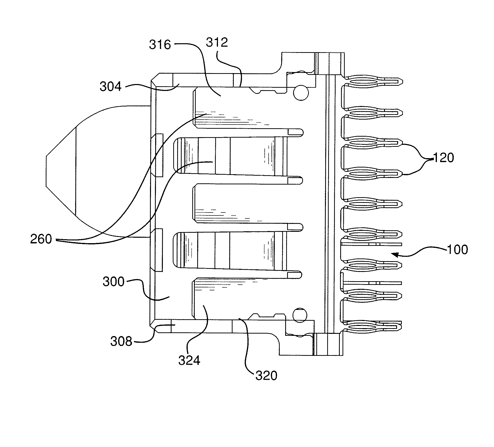
[0019]FIG. 3 depicts an example embodiment of a contact 100 capable of being mounted in a connector housing. The contact 100 may be made from an ...


PUM


Abstract

A connector capable of being mounted onto a substrate is disclosed. Such a connector may include a housing, and a contact mounted within the housing. The contact may include a body, terminal pins extending from a first edge of the body, contact beams extending from a second edge of the body, and a flared portion. The edges of a first contact beam and a second contact beam of the contact beams may be positioned proximate respective adjacent surfaces of the housing. The flared portion may also be positioned proximate a respective adjacent surface of the housing. The relationship between the first contact beam and its respective adjacent surface, the relationship between the second contact beam and its respective adjacent surface, and the relationship between the flared portion and its respective surface may inhibit bowing of the body of the contact when the connector is mounted on the substrate.

Description

CROSS REFERENCE TO RELATED APPLICATIONS[0001]This application is related by subject matter to U.S. patent application Ser. No. 12 / 054,023 filed Mar. 24, 2008, and is also related by subject matter to U.S. patent application Ser. No. 12 / 109,750 filed Apr. 25, 2008.FIELD OF THE INVENTION[0002]Generally the invention relates to electrical connectors. More particularly the invention relates to power connectors.BACKGROUND OF THE INVENTION[0003]A Power connector for transmitting electrical power may be mounted onto a printed circuit board (“PCB”) using a press fit. The press fit application of the connector may generate some concerns about the contact deformation and damage to the housing, especially on a vertical receptacle or header connector. More particularly, if a large enough gap exists between the contact beams of the contacts and the interior walls of the housing, the middle portions of the press-fit tails may arc or bow away from the PCB during mounting of the connector onto the ...

Claims


Application Information

Patent Timeline
Patent Type & Authority Patents(United States)
IPC IPC(8): H01R12/00
CPCH01R12/585
Inventor NGO, HUNG VIETHOUTZ, TIMOTHY W.
Owner FCI AMERICAS TECH LLC
Why Eureka
Try Eureka