Perpendicular stretching method and equipment for optical fiber perform

An optical fiber preform and drawing equipment technology, which is applied to glass manufacturing equipment, manufacturing tools, etc., can solve the problems of uneven heating of the mother rod, increase in production cost, and the influence of size, roundness and bow curvature control, etc. The effect of drawing control accuracy, improving drawing efficiency and reducing production cost

Active Publication Date: 2016-01-06
YANGTZE OPTICAL FIBRE & CABLE CO LTD
View PDF8 Cites 15 Cited by
  • Summary
  • Abstract
  • Description
  • Claims
  • Application Information

AI Technical Summary

Problems solved by technology

Patent document CN1890189A discloses a method and equipment for stretching optical fiber base materials in the horizontal direction. However, the bow of the preform rod cannot be well controlled due to the gravity of the rod itself during the stretching process, which will affect the fiber drawing process. cause more trouble
The patent document CN102627399B discloses a method and equipment for stretching optical fiber base materials in the vertical direction, but in the stretching process, only the size of the rod after stretching is concerned, and the rod reaching 80 mm or more must be melted when heated. It is very slow. When it is detected that the stretching effect is not good, the relevant stretching parameters will be adjusted. After the relevant parameters are adjusted, the impact will be reflected in the stretching effect. Hysteresis; at the same time, the inhomogeneity of the thermal field in the furnace during the heating process of the stretching furnace leads to uneven heating of the master rod during stretching, which will greatly affect the size, roundness and bow control of the preform after stretching. , which leads to a decrease in the drawing efficiency and the geometric and optical properties of the preform or mandrel after stretching, which leads to an increase in production costs and a great waste of raw materials for the preform

Method used


Image

  • Perpendicular stretching method and equipment for optical fiber perform
  • Perpendicular stretching method and equipment for optical fiber perform
  • Perpendicular stretching method and equipment for optical fiber perform

Examples


Embodiment Construction

[0028] The present invention will be further described below in conjunction with accompanying drawing.

[0029] The implementation object of the present invention is a large-diameter optical fiber preform, including a solid-core optical fiber preform, or a core rod, or a combination of a glass sleeve and a core rod. The implementation process is to stretch the large-diameter optical fiber preform into a small-diameter optical fiber preform, the outer diameter of the large-diameter optical fiber preform is between 20 and 200 mm; the outer diameter of the small-diameter optical fiber preform is between 10 and 200 mm. Between 120mm.

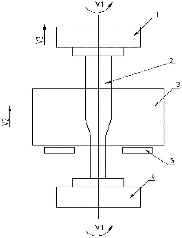
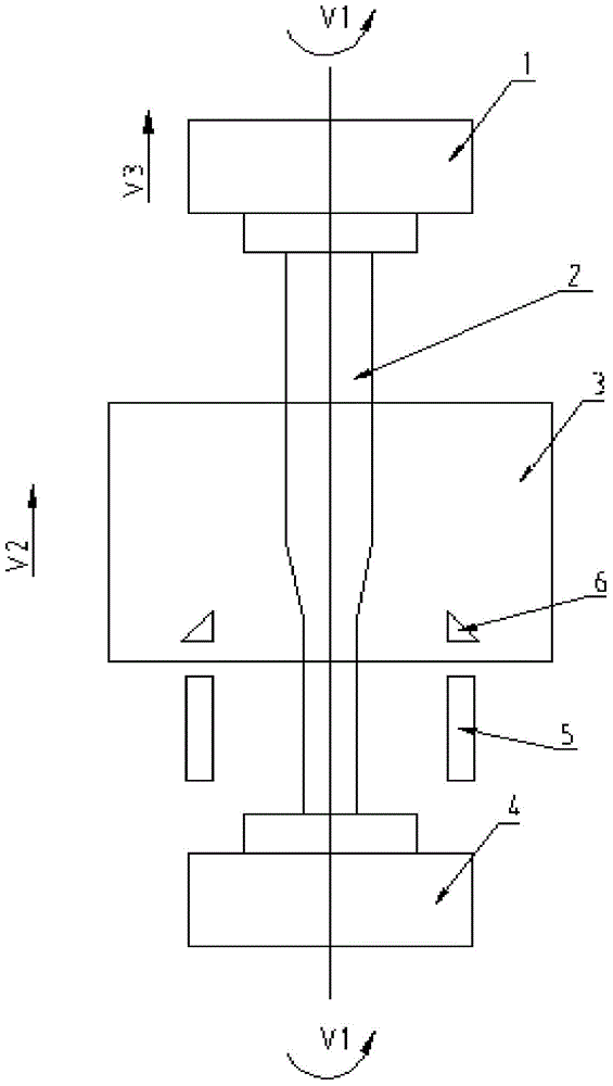
[0030] A vertical stretching device for an optical fiber preform involved in the implementation of the present invention includes an upper clamping device 1, a lower clamping device 4, and a control system. A vacuum system is arranged above the upper clamping device 1. A heating device 3 is installed between the upper and lower clamping devices and...


PUM

PropertyMeasurementUnit
diameteraaaaaaaaaa
diameteraaaaaaaaaa

Abstract

The invention discloses a perpendicular stretching method and equipment for an optical fiber perform. The method comprises the steps that a large-diameter optical fiber perform is clamped, pretreatment starts to be performed on the optical fiber perform, and key parameter values in the stretching process are obtained in advance; then, an upper clamping device and a lower clamping device are controlled to synchronously rotate, the large-diameter optical fiber perform is heated to a semi-molten state through a heating device, an upward moving velocity V<3> is applied to the large-diameter optical fiber perform in the perpendicular direction through the upper clamping device, meanwhile, the heating device moves at an upward velocity V<2>, and the outer diameters obtained before and after stretching meet the relation V<3>*the square of D<1>=V<2>*(the square of D<1>-the square of D<2>). By means of the perpendicular stretching method and equipment for the optical fiber perform, the hysteretic nature in a common real-time feedback adjusting mode can be effectively avoided, the influence of the geometric dimension of the large-diameter optical fiber perform on a stretching result can be reduced to the maximum degree, the stretching control precision is improved, and the machining efficiency is further improved.

Description

technical field [0001] The invention relates to a vertical stretching method and equipment for an optical fiber preformed rod. Background technique [0002] In 1970, Corning of the United States first used the vapor deposition method to prepare preforms and pull out low-attenuation optical fibers. At present, there have been many processing methods for making glass preforms for drawing optical fibers. These processing methods include: external vapor deposition (OVD), vapor axial deposition (VAD), internal vapor deposition (IVD), modified chemical vapor deposition (MCVD), and plasma activated chemical vapor deposition (PCVD). [0003] After decades of technological development, the production capacity of both the optical fiber preform and the core rod of the core material of the preform has changed from a small rod of more than ten millimeters to a large one of more than 150 millimeters that we often see now. For rods, YOFC's prefabricated rods can reach a maximum of 200mm a...

Claims


Application Information

Patent Timeline
Patent Type & Authority Applications(China)
IPC IPC(8): C03B37/012
Inventor 陈武勤何勤国邓睿刘善沛胡琛卢松涛程琼吴骏
Owner YANGTZE OPTICAL FIBRE & CABLE CO LTD
Why Eureka
Try Eureka