
Subcutaneously implantable lead including distal fixation mechanism

Inactive Publication Date: 2011-03-15
MEDTRONIC INC
View PDF18 Cites 62 Cited by
  • Summary
  • Abstract
  • Description
  • Claims
  • Application Information

AI Technical Summary

Problems solved by technology

Withdrawing the sheath from the channel can undesirably snag the lead and move it from is desired subcutaneous position.

Method used


Image

  • Subcutaneously implantable lead including distal fixation mechanism
  • Subcutaneously implantable lead including distal fixation mechanism
  • Subcutaneously implantable lead including distal fixation mechanism

Examples


Embodiment Construction

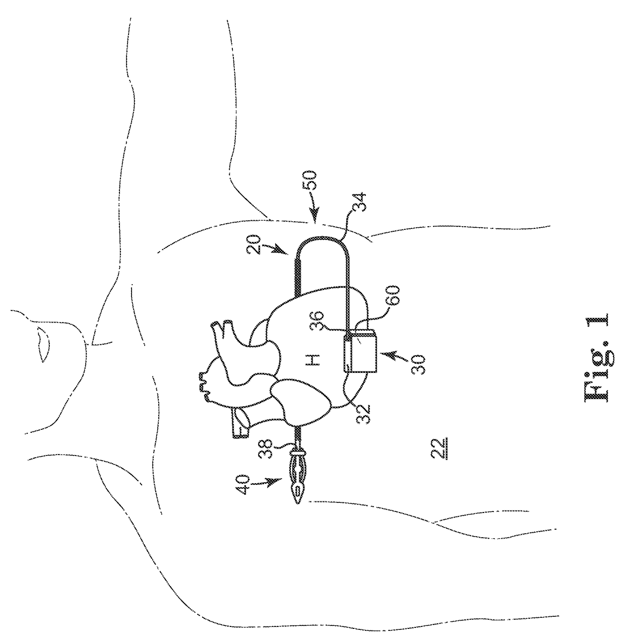
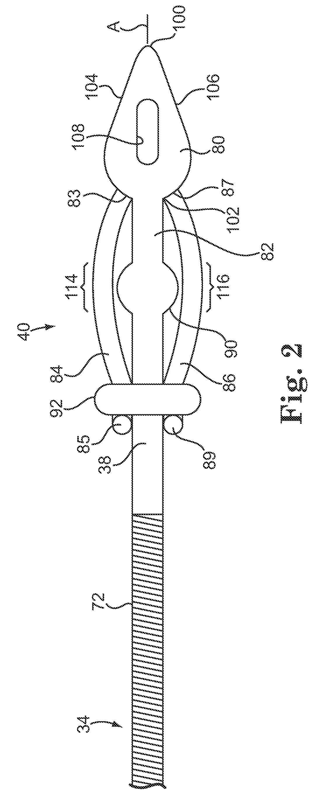
[0016]According to an embodiment of the present invention, a subcutaneously implantable lead is provided that includes a coil disposed along a portion of the lead, and a lead tip coupled to a distal end of the lead. The lead tip includes at least one component that is movable relative to the distal end of the lead and configured to anchor the lead tip in subcutaneous tissue.

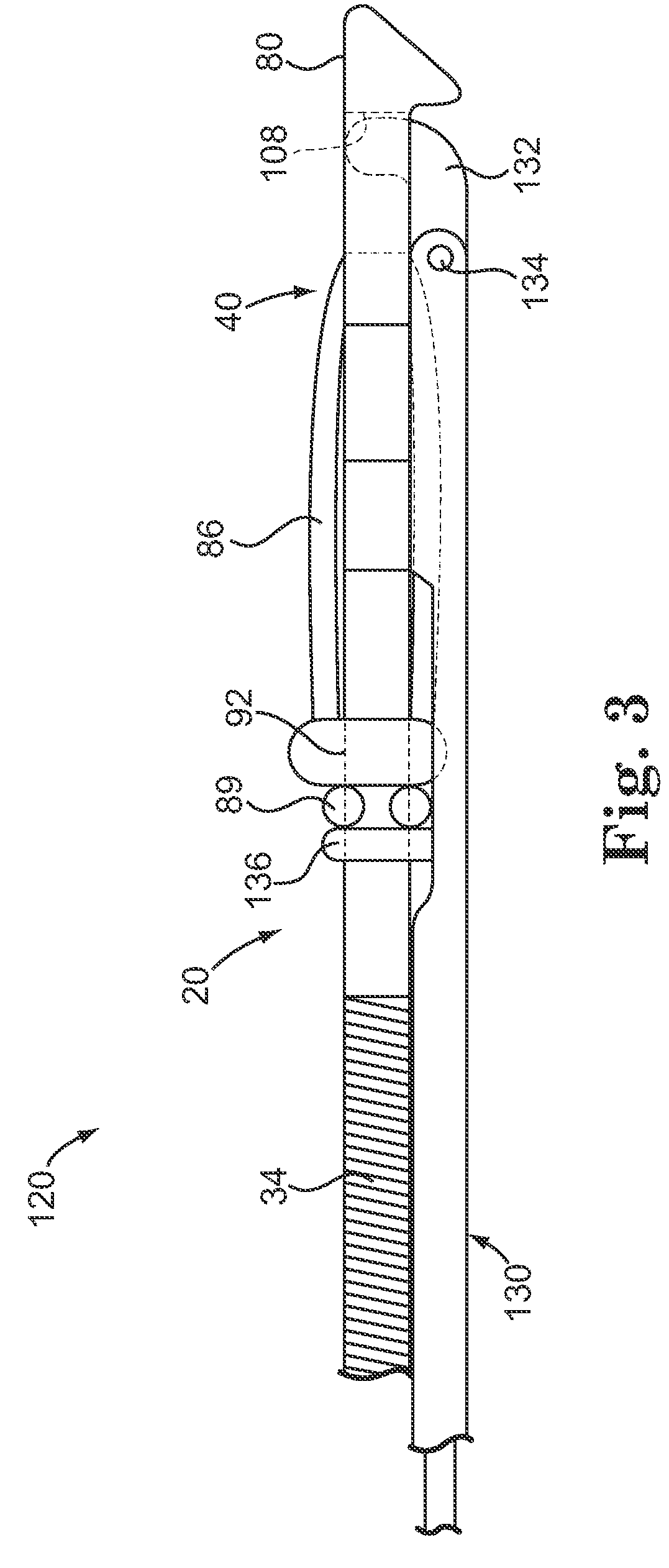
[0017]According to an embodiment of the present invention, a method of implanting a lead in a patient, where the lead is attachable to an implantable cardiodefibrillator (ICD), includes subcutaneously advancing a lead tip attached to a distal end of the lead through a surgical incision formed in the patient's skin with a tunneling tool that is removably attached to the lead tip; and activating a movable portion of the lead tip from a proximal end of the lead to fix the distal end of the lead in subcutaneous tissue.

[0018]In this specification, “anchor” means to fix a position of an object relative to tissue to min...


PUM


Abstract

A subcutaneously implantable lead includes a coil disposed along a portion of the lead, and a lead tip coupled to a distal end of the lead. The lead tip includes at least one component that is movable relative to the distal end of the lead and configured to anchor the lead tip in subcutaneous tissue.

Description

FIELD OF THE INVENTION[0001]The present invention relates generally to subcutaneously implantable leads, and more particularly, to a lead tip having an active distal fixation mechanism employable to subcutaneously secure an implanted lead.BACKGROUND OF THE INVENTION[0002]Many types of implantable medical devices have been clinically implanted into patient's bodies over the last twenty years that deliver relatively high-energy cardioversion and / or defibrillation shocks to a patient's heart when a malignant tachyarrhythmia, e.g., atrial or ventricular fibrillation, is detected. Cardioversion shocks are delivered in synchrony with a detected R-wave when fibrillation detection criteria are met, whereas defibrillation shocks are delivered when fibrillation criteria are met and an R-wave cannot be discerned from the electrocardiogram. The earliest clinically released automatic implantable defibrillators (AIDs) that were implanted in human patients provided a high energy defibrillation sho...

Claims


Application Information

Patent Timeline
Patent Type & Authority Patents(United States)
IPC IPC(8): A61N1/00
CPCA61N1/0504A61N1/057
Inventor LAZEROMS, MARKUS J. C.RUTTEN, JEAN J. G.SMITS, KAREL F. A. A.
Owner MEDTRONIC INC
Learn More