
Proximal interphalangeal joint prothesis

a technology of interphalangeal joint and prothesis, which is applied in the field of interphalangeal joint replacement, can solve the problems of no longer viable joints, further damage to surrounding tissues, and hand or foot pain, and achieve the effect of facilitating osseointegration

Inactive Publication Date: 2017-02-02
JEFFERIS RYAN A +2
View PDF6 Cites 4 Cited by
  • Summary
  • Abstract
  • Description
  • Claims
  • Application Information

AI Technical Summary

Benefits of technology

This patent describes a modular prosthesis for replacing a missing thumb or finger that can be assembled intraoperatively with proximal and distal fixation elements. The prosthesis includes a mobile element that can move relative to the fixation elements in an axis of rotation perpendicular to a plane that extends through the fixation elements. The fixation elements are made using three dimensional printing techniques, which can be scaled according to each patient. This invention addresses the problem of providing a prosthesis that can be customized to the patient's individual needs.

Problems solved by technology

PIP joints, such as those of the hands or feet, can be damaged by trauma, injury and / or by disease such as osteoarthritis, such that the joint is no longer viable.
Direct attachment of the replacement joint to the bone makes revision, i.e. replacement of the prosthesis, in instances of replacement joint failure difficult and can further damage the surrounding tissue.
Due to the stresses placed on the joint, insufficient lateral stability, and expected implant survival rates, one alternative approach to PIP replacement is to fuse the joint rather than replace the joint.
Current approaches are moderately successful in alleviating pain and restoring cosmetic appearance, but are prone to failure and maintain only a nominal range of motion.
Tissue damage including both the bone and surrounding tissue can be difficult to assess prior to the operative procedure.
Prostheses are manufactured according to various sizes and the range of sizes limited by cost, e.g. more sizes available to choose from means more devices produced than needed, and fewer sizes are limited by proper functioning of the prostheses in terms of range of motion, gripping strength, lateral stability, etc.
Dissatisfaction with existing PIP replacement joints includes failure due to mechanical failure, dislocation, and / or limited range of motion.
Mechanical failures, such as fracturing of the implanted joint, can occur due to repetitive motion and stresses placed on the joint.
The loosening and migration can further damage surrounding tissue and affect continued viability of the joint operation.

Method used


Image

  • Proximal interphalangeal joint prothesis
  • Proximal interphalangeal joint prothesis
  • Proximal interphalangeal joint prothesis

Examples


Embodiment Construction

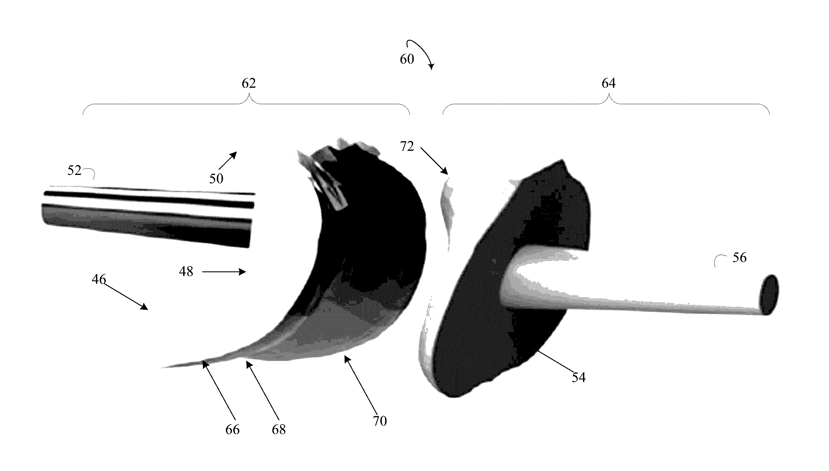
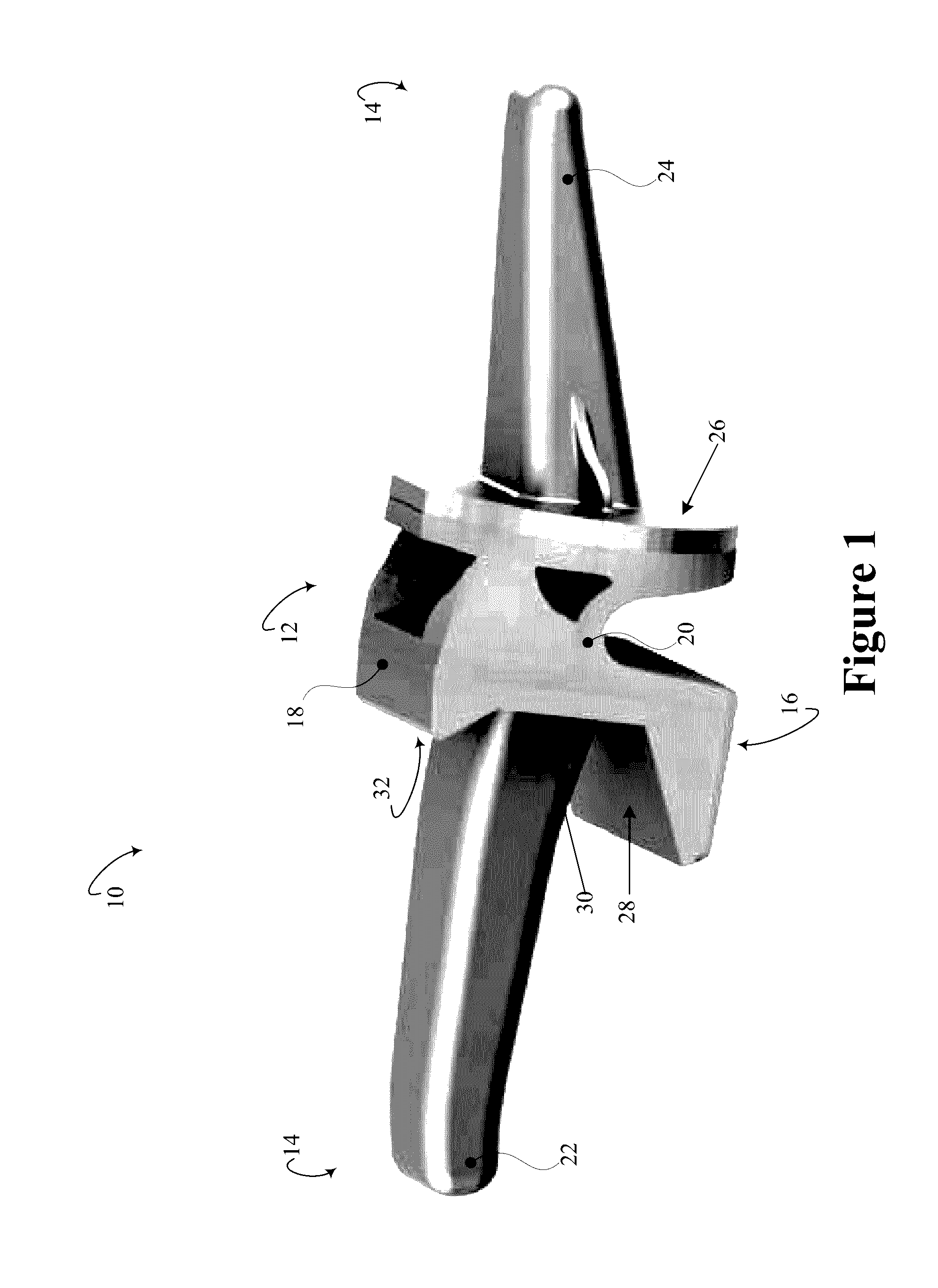
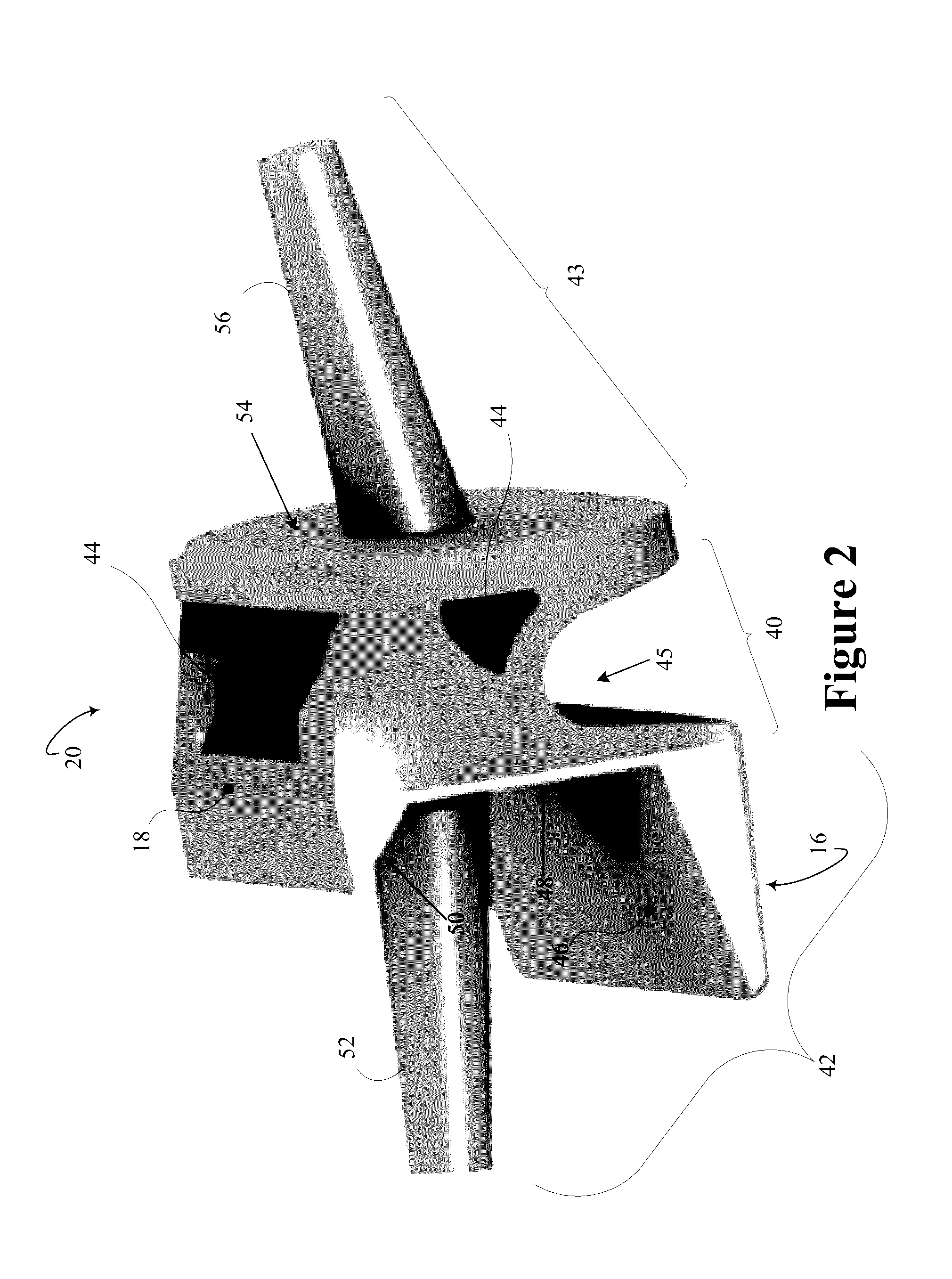
[0020]Initially referring to FIG. 1, an example modular PIP prosthesis 10 in a perspective view with a mobile element 12 coupled to fixation elements 14 is schematically illustrated. The modular PIP prosthesis 10 is manufactured from one or more biocompatible materials. The view of the modular PIP prosthesis 10 is oriented with palmar surfaces 16, i.e. facing the same direction as palm of the hand, and dorsal surfaces 18, i.e. facing the same direction as the back of the hand. The mobile element 12 includes a constrained mobile element 20. The modular PIP prosthesis 10 includes fixation elements 14 which are coupled to the constrained mobile element 12. The mobile element 12 can include an unconstrained element or a partially constrained element. The mobile element 12 can be selected intraoperatively from the unconstrained, partially constrained, and constrained mobile elements. In some instances, the selection can be guided by a state of soft tissue. For example, an unconstrained m...


PUM


Abstract

An interphalangeal prosthesis (10) includes a mobile element (12), a proximal fixation element (22), and a distal fixation element (24). The mobile element (12) includes a proximal portion (42, 62, 94) and a distal portion (43, 64, 92), and the proximal portion includes three proximal mobile coupling contiguous surfaces (46, 48, 50) and a proximal mobile coupling protrusion (52), and the distal portion includes a distal coupling mobile surface (54) and a distal mobile coupling protrusion (56), and the proximal portion and the distal portion move relative to each other primarily in an axis of rotation perpendicular to a plane that extends through the proximal mobile coupling protrusion, the three proximal mobile coupling contiguous surfaces, the distal coupling mobile surface, and the distal mobile coupling protrusion in an implanted configuration. The proximal fixation element (22) couples to the three proximal mobile coupling contiguous surfaces and the proximal mobile coupling protrusion of proximal portion, and couples to a joint bone surface and a bone canal. The distal fixation element (24) couples to the distal coupling mobile surface and the distal mobile coupling protrusion, and couples to an opposing joint bone surface and a second bone canal.

Description

FIELD OF THE INVENTION[0001]The following generally relates to interphalangeal joint replacement, and is described with particular application to a proximal interphalangeal (PIP) joint replacement apparatus and method of construction.BACKGROUND OF THE INVENTION[0002]PIP joints, such as those of the hands or feet, can be damaged by trauma, injury and / or by disease such as osteoarthritis, such that the joint is no longer viable. PIP joints differ from other joints in that the range of motion occurs generally within a single plane, e.g. flexion without significant lateral rotation that occurs with other joints, such as with a shoulder or a hip. A healthy range of motion includes 0-5 degrees in extension to 100-115 degrees in flexion. A functional range of motion is 36-86 degrees in flexion, and an acceptable outcome for PIP arthroplasty is 50-70 degrees in flexion.[0003]Existing replacement joints or prostheses typically are integrated devices which includes an affixed attachment mecha...

Claims


Application Information

Patent Timeline
IPC IPC(8): A61F2/42A61F2/30
CPCA61F2/4241A61F2/30771A61F2002/4248A61F2002/30878A61F2310/00029A61F2002/3092A61F2240/001A61F2310/00023A61F2002/30624A61F2/30942A61F2/4225A61F2002/30069A61F2002/30448A61F2002/30884A61F2002/30962A61F2002/4228A61F2002/4243
Inventor JEFFERIS, RYAN A.CHIN, MICHELLE A.FIELDS, ROBERT (AKA ANDREW) A.
Owner JEFFERIS RYAN A
Learn More