
Trans-anal inflow catheter for intermittently triggering a reflex-coordinated defecation

a transanal inflow and reflex-coordinated technology, which is applied in the field of devices for transanal infusion into, can solve the problems of not contributing to a better stimulation, impairing the transanal positioning of the device, etc., and achieve the effect of avoiding uncontrolled deep insertion

Inactive Publication Date: 2018-11-01
ADVANCED MEDICAL BALLOONS GMBH
View PDF13 Cites 4 Cited by
  • Summary
  • Abstract
  • Description
  • Claims
  • Application Information

AI Technical Summary

Benefits of technology

The invention solves the problem of catheter tip perforating the bowel wall by limiting the position of the tip to the difference in diameter between the transanal and the intrarectal balloon segments, and by gripping the catheter shaft in the preanal region to avoid uncontrolled deep insertion. This minimizes the risk of injury and ensures the safe and reliable placement of the tapered portion of the balloon.

Problems solved by technology

A diameter increase beyond the preshaped dimension would be potentially impairing the trans-anal positioning of the device and not contributing to a better stimulation result.

Method used


Image

  • Trans-anal inflow catheter for intermittently triggering a reflex-coordinated defecation
  • Trans-anal inflow catheter for intermittently triggering a reflex-coordinated defecation
  • Trans-anal inflow catheter for intermittently triggering a reflex-coordinated defecation

Examples


Embodiment Construction

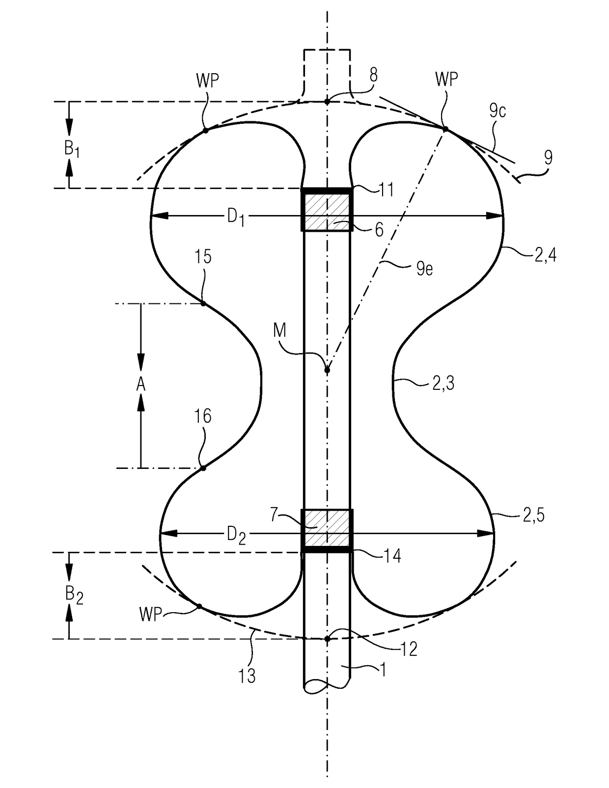
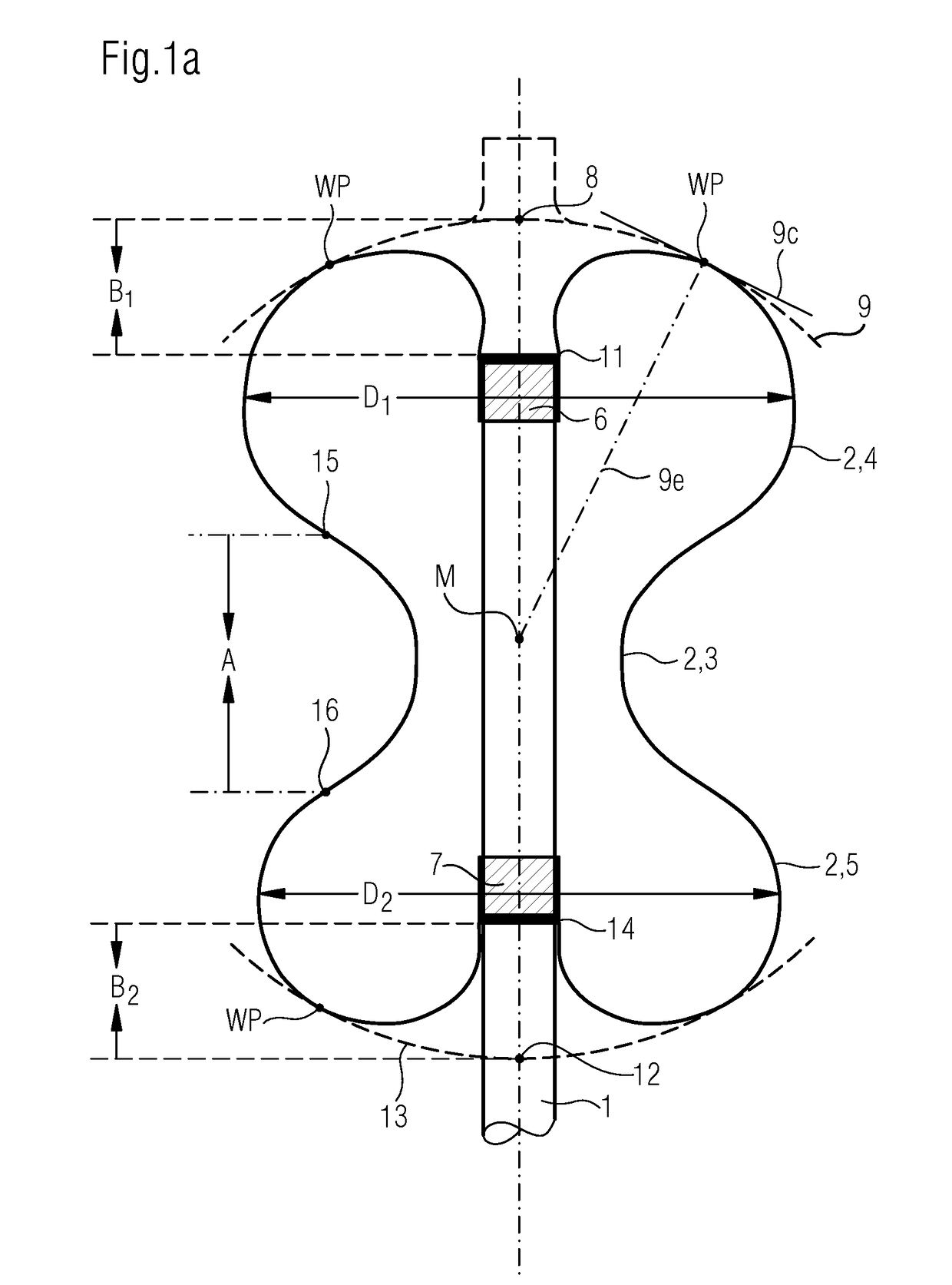
[0056]FIG. 1a shows a longitudinal section through an inflow catheter with a dumbbell- or hourglass-shaped balloon element 2 disposed at the distal end of the catheter shaft 1. The balloon element has, for example, a spherical or discoid expansion at each end. Disposed in the middle region between the terminal enlargements is a cylindrically or approximately cylindrically shaped segment 3 of reduced diameter, which continuously connects the intrarectal enlargement 4 to the preanal enlargement 5.

[0057]The balloon 2 terminally comprises two balloon shaft ends (6, 7) for attaching the balloon to the shaft. During the mounting of the balloon, the shaft ends 6 and 7 are invaginated (inverted) into the inside of the balloon by a defined magnitude B and in this position, in which they are displaced toward each other, are fixed on the shaft 1, for example by gluing or welding.

[0058]The sum of the magnitudes B of the inversions at both ends should be at least equal to the length of the taper...


PUM


Abstract

The invention relates to a device for transanally introducing an infusion into the rectum or colon of a patient, said device comprising a catheter with a catheter shaft and an inflatable balloon, comprising a distal terminal balloon section of larger radius and generally spherical or discoid shape, and, disposed proximal to this distal terminal balloon section, a tapered balloon section having a reduced radius, the tapered balloon section of the device being adapted to be placed transanally, such that the enlarged distal terminal balloon section is placed intrarectally wherein the balloon is fixed onto the catheter shaft only at fixation points located at the ends of the balloon, wherein both balloon ends taper approximately to a shaft dimension of the catheter shaft supporting the balloon; according to the present invention, the difference between the larger radius of the distal terminal balloon section and the reduced radius of the proximally adjacent, tapered balloon section is either in the pressurized state of the balloon at 30 mbar, smaller than the difference between the larger radius of the distal terminal balloon section and the reduced radius of the proximally adjacent, tapered balloon section in the pressurized state of the balloon at 100 mbar, or is in the inflated, but unpressurized state of the balloon greater than the distance between the distal end of the catheter shaft on the one hand and the distal fixation point of the balloon to the catheter shaft on the other hand.

Description

REFERENCE TO PENDING PRIOR PATENT APPLICATIONS[0001]This patent application is a continuation-in-part of pending prior U.S. patent application Ser. No. 14239,991, filed Feb. 20, 2014 by Fred Gebel for TRANS-ANAL INFLOW CATHETER AND METHOD FOR INTERMITTENTLY TRIGGERING A REFLEX-COORDINATED DEFECATION (Attorney's Docket No. KUCH-59), which in turn is a 371 national stage entry of International (PCT) Patent Application No. PCTEP2012003535, filed Aug. 20, 2012 by Fred Gebel for TRANS-ANAL INFLOW CATHETER AND METHOD FOR INTERMITTENTLY TRIGGERING A REFLEX-COORDINATED DEFECATION, which patent application in turn: (i) claims benefit of prior German Patent Application No. 10 2011 111 225.5, filed Aug. 20, 2011; (ii) claims benefit of prior German Patent Application No. 10 2011 118 943.6, filed Nov. 21, 2011; (iii) claims benefit of prior German Patent Application No. 10 2011 121 202.0, filed Dec. 16, 2011; (iv) claims benefit of prior German Patent Application No. 10 2012 005 607.9, filed Ma...

Claims


Application Information

Patent Timeline
Patent Type & Authority Applications(United States)
IPC IPC(8): A61M25/10A61F2/00
CPCA61M25/1002A61F2/0013A61M25/10186A61M25/1029A61M3/0295A61M2025/1052A61M25/09041A61M2025/0687A61M25/1009A61M2210/1067A61M3/0262A61M2210/1064A61M25/10187A61M3/0208A61M3/022A61M3/0245
Inventor GOBEL, FRED
Owner ADVANCED MEDICAL BALLOONS GMBH
Learn More