Double row ball bearing and differential gear device

a technology of differential gear and ball bearing, which is applied in the direction of rotary machine parts, mechanical equipment, and bearing details, can solve the problems of reducing the running torque of the bearing in order to achieve a low-loss design, and achieve the effect of reducing the diameter of the smaller diameter-side ball, reducing the contact angle, and reducing the revolution speed

Inactive Publication Date: 2011-03-22
JTEKT CORP
View PDF6 Cites 6 Cited by
  • Summary
  • Abstract
  • Description
  • Claims
  • Application Information

AI Technical Summary

Benefits of technology

[0008]It is an object of this invention to provide a double row ball bearing device in which a flow of lubricating oil in the bearing is rectified, thereby enabling a low-torque design.
[0017]The difference between the revolution period of the larger diameter-side balls and the revolution period of the smaller diameter-side balls can be made small, for example, by increasing the diameter of the larger diameter-side balls while the diameter and contact angle of the smaller diameter-side balls and the pitch circle diameters of the two rows of balls are kept the same as those of a conventional bearing. Additionally, it is preferred to decrease the contact angle of the larger diameter-side balls. This can also be achieved merely by making the contact angle of the larger diameter-side balls smaller than the contact angle of the smaller diameter-side balls while keeping the diameter of the larger diameter-side balls equal to the diameter of the smaller diameter-side balls. When the contact angle is increased, a differential slip (spin) at an area of contact between the ball and the raceway surface increases, and the revolution speed decreases. Therefore, merely by changing the contact angle, the revolution period can be adjusted. Furthermore, the diameter of the smaller diameter-side balls may be decreased (in which case the number of the balls increases), and also the contact angle of the smaller diameter-side balls may be increased. Furthermore, the difference in pitch circle diameter between the row of larger diameter-side balls and the row of smaller diameter-side balls may be slightly reduced.
[0018]Preferably, the contact angles are so determined that the relation, (β−10)≦α<β, is established where α(°) represents the contact angle of the larger diameter-side ball, and β(°) represents the contact angle of the smaller diameter-side ball. When α=(β−5) is established, an axial rigidity of the large diameter-side balls is generally equal to an axial rigidity of the small diameter-side balls, and the life of the large diameter-side balls used under a large axial load can be prevented from being shortened. For preventing the shortened life of the large diameter-side balls used in such a large axial load, it is also effective to make a curvature of the larger-diameter raceway larger than a curvature of the smaller-diameter raceway.
[0019]In case the difference in revolution period between the larger diameter side and the smaller diameter-side is large, a flow of lubricating oil at the larger-diameter side and a flow of lubricating oil at the smaller-diameter side interfere with each other within the bearing, so that the flow becomes complicated, thereby increasing a bearing torque. By synchronizing the two revolution periods with each other, the flow of the lubricating oil in the bearing can be rectified, so that the running torque of the bearing can be reduced.
[0020]More preferably, in order to secure the flow of the lubricating oil from the smaller-diameter side to the larger-diameter side, the pitch circle diameter of the larger diameter-side balls is made larger than the pitch circle diameter of the smaller diameter-side balls, and the two revolution periods are made equal to each other. By doing so, the flow of the lubricating oil in the bearing can be optimized so as to reduce the running torque, and besides the two cages used respectively at the larger-diameter side and the smaller-diameter side can be replaced by a single cage, and therefore the number of the component parts can be reduced.
[0021]In the double row ball bearing of the present invention, the difference between the revolution period of the larger diameter-side balls and the revolution period of the smaller diameter-side balls is small, and therefore the flow of the lubricating oil in the bearing can be rectified, thereby enabling the low-torque design.

Problems solved by technology

In a pinion shaft support apparatus of a vehicle, etc., to reduce a running torque of a bearing in order to achieve a low-loss design has been a problem.

Method used


Image

  • Double row ball bearing and differential gear device
  • Double row ball bearing and differential gear device
  • Double row ball bearing and differential gear device

Examples


Embodiment Construction

[0025]Preferred embodiments of the present invention will now be described with reference to the drawings.

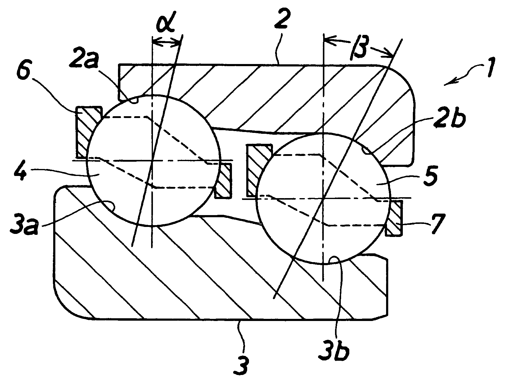
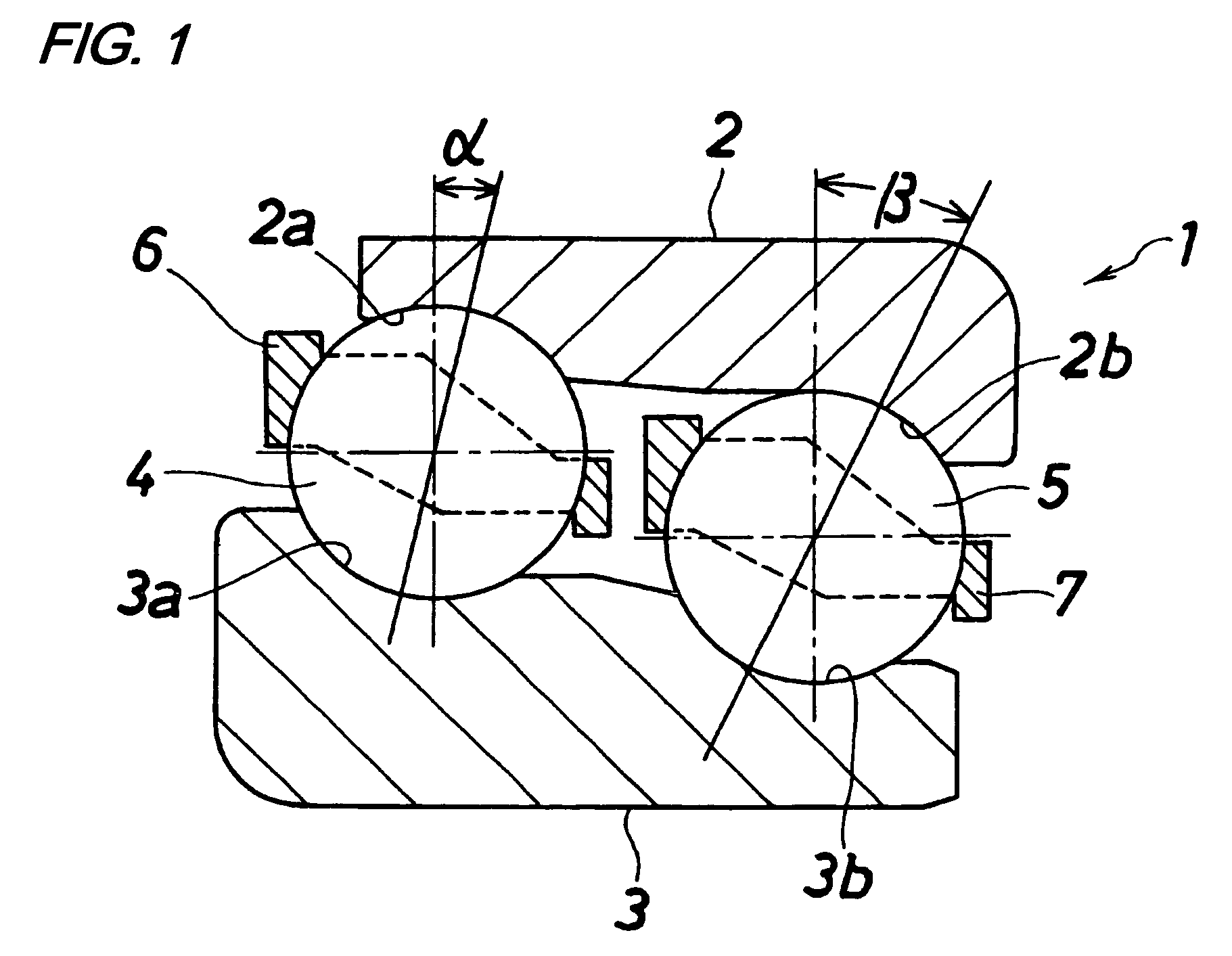
[0026]FIG. 1 shows a first embodiment of a double row ball bearing of the present invention. This double row ball bearing 1 comprises an outer ring 2 which has two raceway surfaces 2a and 2b different in diameter from each other and is adapted to be mounted on a housing (not shown), an inner ring 3 which has two raceway surfaces 3a and 3b corresponding respectively to the raceway surfaces 2a and 2b of the outer ring 2 and is adapted to be mounted on a rotation shaft (not shown), a row of larger diameter-side balls 4 disposed between the raceway surface 2a of the outer ring 2 and the raceway surface 3a of the inner ring 3, a row of smaller diameter-side balls 5 which are disposed between the raceway surface 2b of the outer ring 2 and the raceway surface 3b of the inner ring 3 and have a pitch circle diameter smaller than a pitch circle diameter of the larger diameter-side balls 4...


PUM


Abstract

The difference between a revolution period of larger diameter-side balls and a revolution period of smaller diameter-side balls is smaller as compared with a conventional bearing. The relation, (β−10)≦α<β, is established, where α(°) represents a contact angle of the larger diameter-side ball, and β(°) represents a contact angle of the smaller diameter-side ball.

Description

BACKGROUND OF THE INVENTION[0001]1. Field of the Invention[0002]This invention relates to a double row ball bearing, and more particularly to a double row ball bearing (called a tandem type) which can suitably support a pinion shaft, for example, of a final reduction gear of an automobile, and is lubricated by lubricating oil received within the final reduction gear.[0003]2. Related Art[0004]Tandem type double row ball bearings which include a plurality of balls arranged in two rows between an outer ring and an inner ring, and a cage holding these balls have been extensively used in a pinion shaft support apparatus for a vehicle, etc., as shown in JP-A-2006-234100.[0005]FIG. 3 shows a differential gear device which is one example of apparatus in which a double row ball bearing of the present invention can be used. The differential gear includes a pinion shaft 42 rotatably supported on a housing 41 and having a pinion gear 43 provided at a rear end thereof, a ring gear 44 meshing wit...

Claims


Application Information

Patent Timeline
Patent Type & Authority Patents(United States)
IPC IPC(8): F16C19/08
CPCF16C19/182F16C19/56F16C2240/80F16C2361/61F16C19/505F16C19/548
Inventor TAKIMOTO, ATSUSHITANIGUCHI, YOUZOU
Owner JTEKT CORP
Why Eureka
Try Eureka