Tapered roller bearing

a technology of tapered roller bearings and tapered rollers, which is applied in the direction of rolling contact bearings, shafts and bearings, rotary bearings, etc., can solve the problem of reducing the amount of shifting of lubricating achieves the reduction of the amount of shifting of lubricating oil toward the outer ring, the effect of reducing the amount of shifting of lubricating oil and easy supply

Inactive Publication Date: 2009-01-29
JTEKT CORP
View PDF10 Cites 5 Cited by
  • Summary
  • Abstract
  • Description
  • Claims
  • Application Information

AI Technical Summary

Benefits of technology

[0008]It is an object of this invention to provide a tapered roller bearing in which even when the amount of lubricating oil within the tapered roller bearing is much reduced, a large rib of an inner ring is less liable to undergo seizure, thereby achieving both of a low-torque design and a seizure resistance.

Problems solved by technology

However, each guide groove receives the lubricating oil by its bottom surface and opposed side surfaces, and reduces the amount of the lubricating oil shifting toward the outer ring.

Method used


Image

  • Tapered roller bearing
  • Tapered roller bearing
  • Tapered roller bearing

Examples


first embodiment

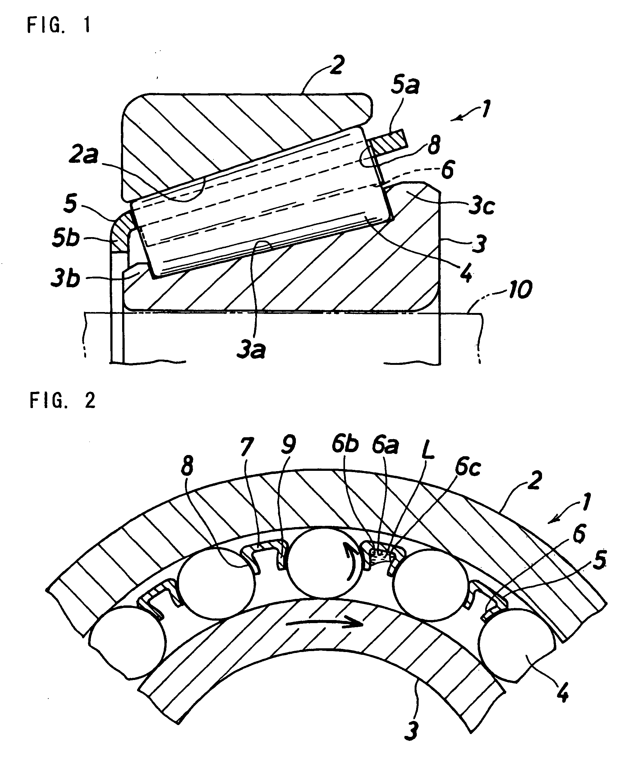
[0026]FIGS. 1 and 2 show a tapered roller bearing of the invention. This tapered roller bearing 1 comprises an outer ring 2 to be mounted on a housing (not shown), an inner ring 3 to be mounted on a rotation shaft 10, a plurality of tapered rollers 4 disposed between the outer and inner rings 2 and 3, and a cage 5 holding the tapered rollers 4.

[0027]The inner ring 3 has a tapered raceway surface 3a, and a small rib 3b for limiting an axial movement of the tapered rollers 4 is formed at a left end portion of the raceway surface 3a, while a large rib 3c for limiting the axial movement of the tapered rollers 4 is formed at a right end portion of the raceway surface 3a.

[0028]The outer ring 2 has a tapered raceway surface 2a, and a right end face of the outer ring 2 is disposed inwardly of a right end face of the inner ring 3.

[0029]The cage 5 includes a larger-diameter end portion 5a projecting right beyond the tapered rollers 4, and a smaller-diameter end portion 5b projecting left bey...

third embodiment

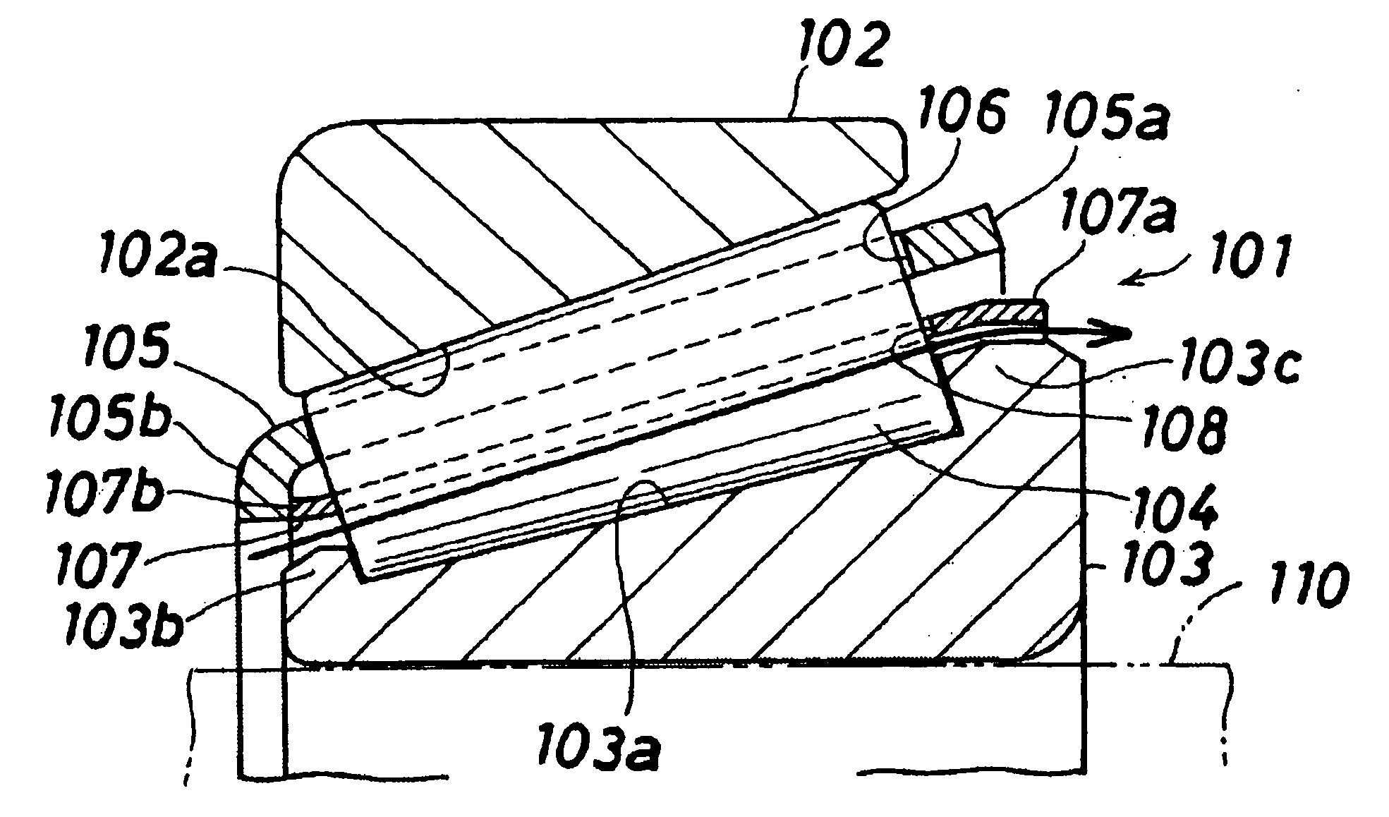
[0039]FIGS. 5 and 6 show a tapered roller bearing according to the invention. This tapered roller bearing 101 comprises an outer ring 102 to be mounted on a housing (not shown), an inner ring 103 to be mounted on a rotation shaft 110, a plurality of tapered rollers 104 disposed between the outer and inner rings 102 and 103, a cage 105 holding the tapered rollers 104, and a guide member 107 disposed between the cage 105 and the inner ring 103 so as to reduce the amount of shifting of lubricating oil toward the outer ring 102.

[0040]The inner ring 103 has a tapered raceway surface 103a, and a small rib 103b for limiting an axial movement of the tapered rollers 104 is formed at a left end portion of the raceway surface 103a, while a large rib 103c for limiting the axial movement of the tapered rollers 104 is formed at a right end portion of the raceway surface 103a.

[0041]The outer ring 102 has a tapered raceway surface 102a, and a right end face of the outer ring 102 is disposed inward...


PUM


Abstract

Guide grooves for guiding lubricating oil from a small rib-side end portion of an inner ring to a large rib-side end portion thereof are formed at an inner periphery of a cage.

Description

BACKGROUND OF THE INVENTION[0001]This invention relates to a tapered roller bearing, and more particularly to a tapered roller bearing which supports a pinion shaft, for example, of a final reduction gear of an automobile, and is lubricated by lubricating oil received within this final reduction gear.[0002]A tapered roller bearing (see JP-A-2005-69421) which includes a plurality of tapered rollers disposed between an outer ring and an inner ring, and a cage holding these tapered rollers is compact, and can support large radial and axial loads, and besides can be used at a high rotational speed. Therefore, such tapered roller bearings have been extensively used in a pinion shaft support apparatus for a vehicle, etc., as shown in JP-A-2000-170775.[0003]FIG. 7 shows a differential gear apparatus of the type in which a tapered roller bearing of the present invention can be used. The differential gear apparatus includes a pinion shaft 42 rotatably supported on a housing 41 and having a p...

Claims


Application Information

Patent Timeline
Patent Type & Authority Applications(United States)
IPC IPC(8): F16C33/46F16H57/021F16H57/037
CPCF16C19/364F16C33/54F16C33/6681F16C2361/61F16H57/037F16H57/0471F16H57/0483F16H57/021F16C33/543F16C33/547
Inventor SADA, TAKASHIMATSUYAMA, HIROKI
Owner JTEKT CORP
Why Eureka
Try Eureka