Electrostatic spray nozzle with adjustable fluid tip and interchangeable components

a technology of fluid tip and charging nozzle, which is applied in the direction of electrostatic spraying apparatus, burners, lighting and heating apparatus, etc., can solve the problems of spraying being misdirected in the slipstream, and achieve the optimization of charging and spray quality, accurate axial movement, and increase the useable range of liquid flow rate

Active Publication Date: 2011-03-29
SUNLESS
View PDF85 Cites 35 Cited by
  • Summary
  • Abstract
  • Description
  • Claims
  • Application Information

AI Technical Summary

Benefits of technology

[0011]An electrostatic spray charging nozzle according to at least one embodiment of the present invention comprises a liquid tip that can be accurately axially moved and set during operation of the nozzle to optimize charging and spray quality in both induction charging and contact charging configurations, as well as to increase the useable range of liquid flow rates and to reduce the effects of normal manufacturing variations. In addition, the key components of the nozzle in accordance with embodiments of the present invention can be easily removed and interchanged with those of other nozzles without affecting charging or spray quality. In one embodiment, the nozzle can be operated as a contact charging device by applying a voltage directly to the liquid. In an alternate embodiment, the nozzle can be operated as an induction charging device where a voltage is applied to the air cap / electrode and the spray liquid is earthed (grounded) near the nozzle. In accordance with at least one embodiment the air cap / electrode is easily removed from the retaining cap for replacement or substitution for a cap of a different geometry.

Problems solved by technology

Manufacturing variations or normal wear of either of these parts can cause droplet size and charging variations, as well as cause the spray to be misdirected in the slipstream of the atomization channel.

Method used


Image

  • Electrostatic spray nozzle with adjustable fluid tip and interchangeable components
  • Electrostatic spray nozzle with adjustable fluid tip and interchangeable components
  • Electrostatic spray nozzle with adjustable fluid tip and interchangeable components

Examples


Embodiment Construction

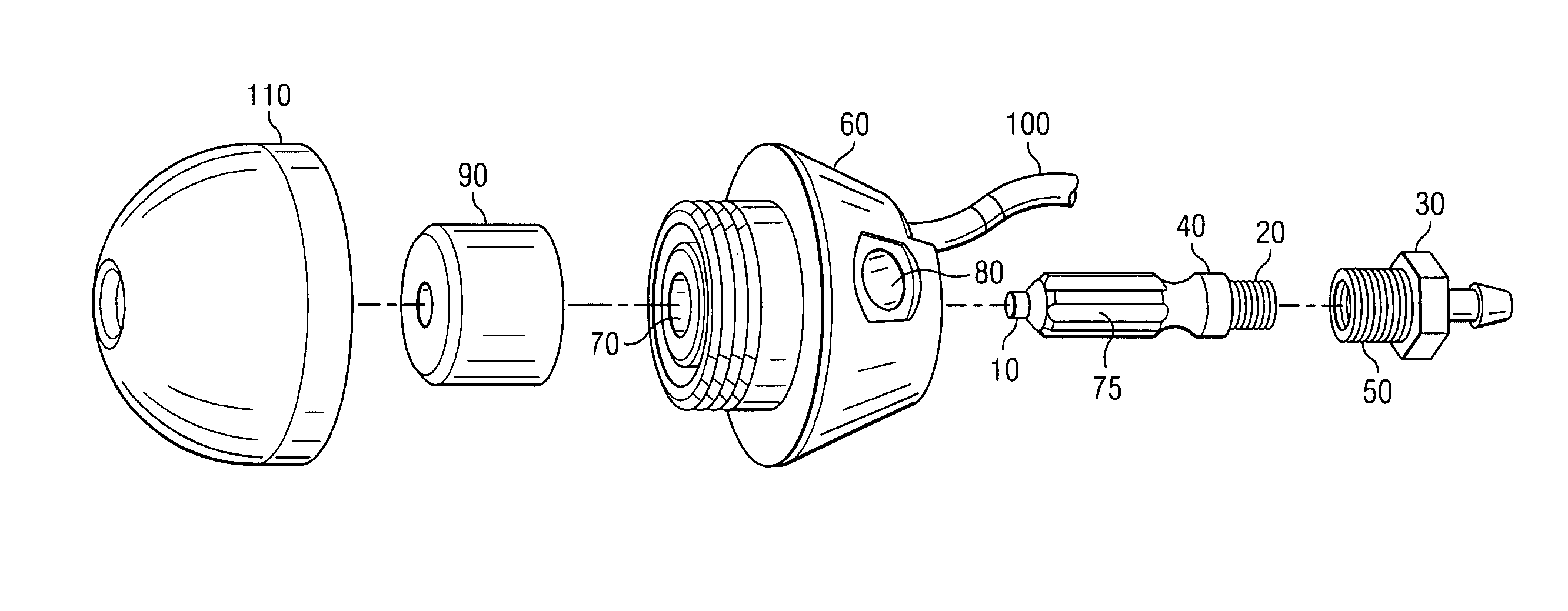
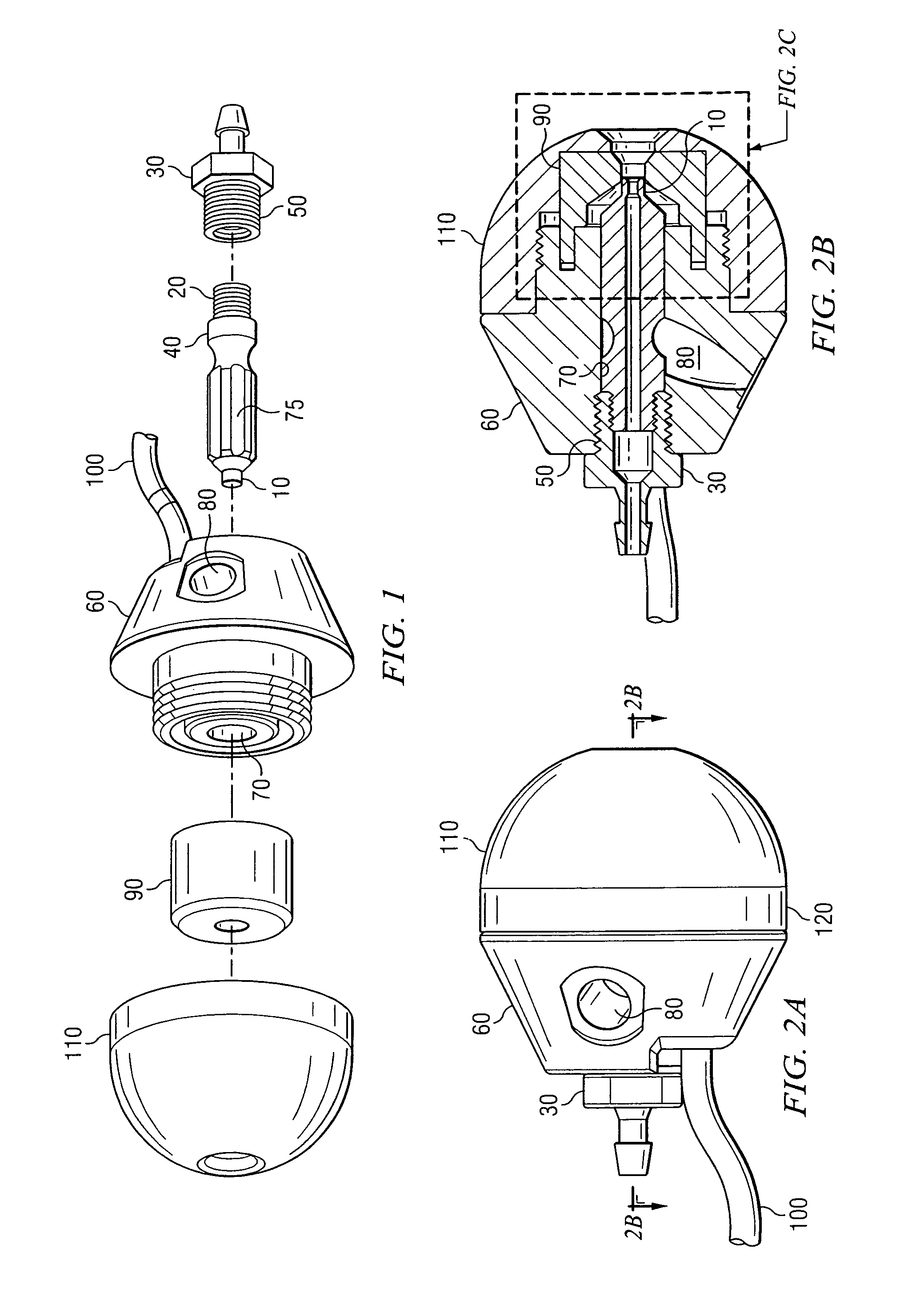
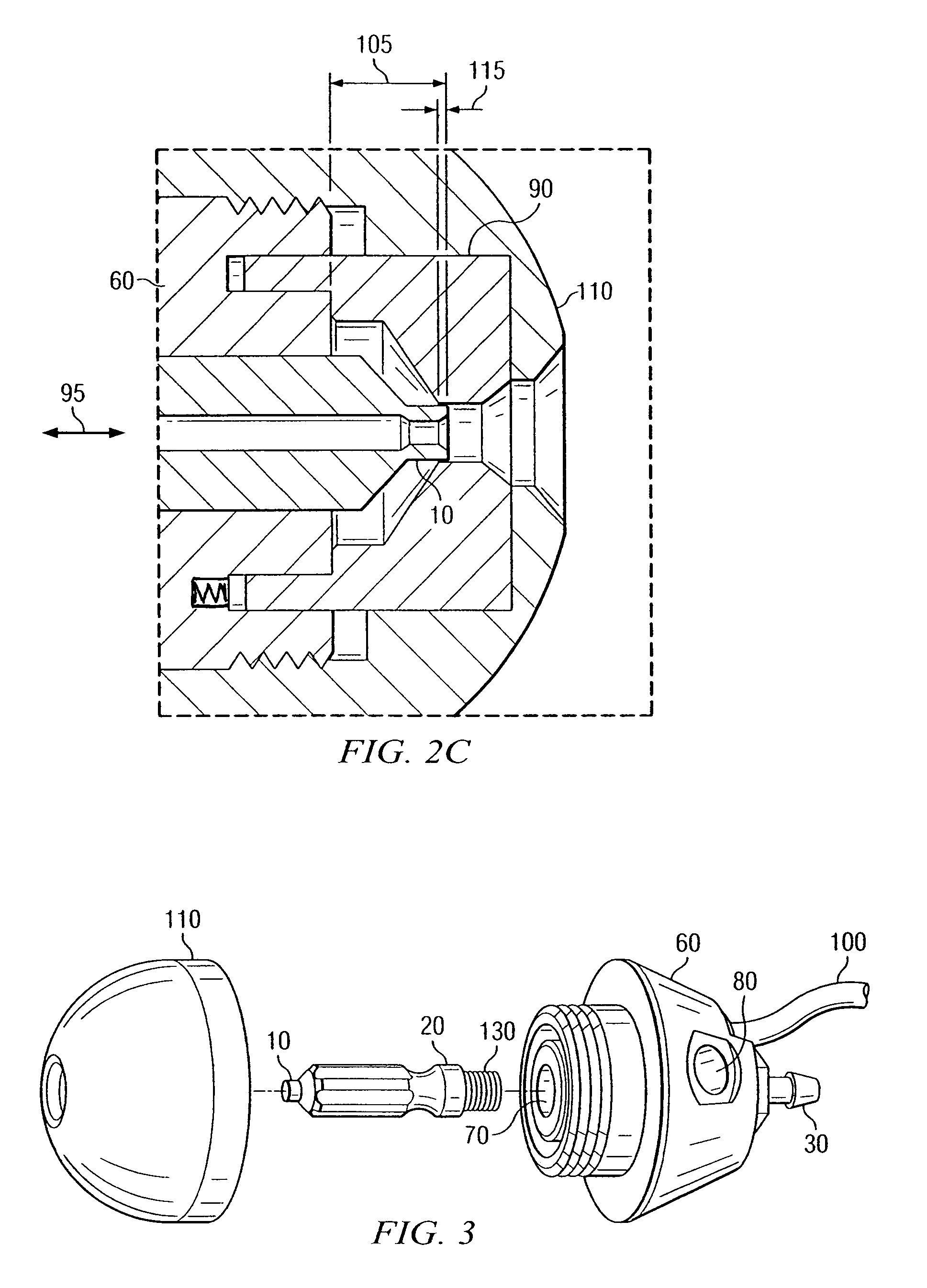
[0025]Referring now to FIG. 1, an embodiment of a nozzle of the present invention is illustrated in which a fluid tip 10 having a fluid tip base 20 with a threaded end is screwed into an inner threaded portion of a liquid inlet connector 30. In accordance with some embodiments of the present invention, the fluid tip can be comprised of a dielectric material. A sealing boss 40 on the fluid tip 10 provides for liquid sealing between the fluid tip 10 and the liquid inlet connector 30. The liquid inlet connector 30 is further provided with fluid tip length adjustment threads 50 along an outer circumference. The liquid inlet connector 30 is adapted to be connected to a source of spray liquid. The fluid tip length adjustment threads 50 are adapted to allow the liquid inlet connector 30 to be threaded into a back surface of a nozzle body 60. With the fluid tip 10 mounted to the liquid inlet connector 30, the selective threading of the liquid inlet connector 30 result in an adjustment in th...


PUM


Abstract

An electrostatic spray charging nozzle designed for optimum charge level over a wide range of liquid and air flow rates. The electrostatic spray charging nozzle includes a nozzle cap having an outlet, a nozzle body having a first bore, and a fluid tip assembly extending at least partially through the first bore. The fluid tip assembly further includes a liquid inlet adapted to be connected to a source of liquid, and a liquid outlet adapted to dispense the liquid through the outlet of the nozzle body. The electrostatic spray charging nozzle further includes an adjustment mechanism operable to move the fluid tip assembly within the first bore so as to adjust a longitudinal distance between the liquid outlet of the fluid tip assembly and the outlet of the nozzle cap.

Description

CROSS-REFERENCE TO RELATED APPLICATIONS[0001]This application claims priority from and incorporates by reference the entire disclosure of U.S. Provisional Application No. 60 / 627,191 filed Nov. 12, 2004 and U.S. Provisional No. 60 / 627,480 filed Nov. 12, 2004.BACKGROUND OF THE INVENTION[0002]Embodiments of the present invention relate to electrostatic spray charging of conductive liquids, in particular to air-atomizing spray charging nozzles for conductive liquids that use the principles of induction or contact charging.[0003]Electrostatic charging nozzles are well known and in widespread use in a number of commercial applications. Nearly every vehicle manufactured worldwide is painted electrostatically. Most of these industrial electrostatic spray systems charge spray by ionization and dispense powder or non-conductive liquids. There is a need for electrostatic spray devices that can reliably charge electrically conductive formulations, such as those that are water based. Several typ...

Claims


Application Information

Patent Timeline
Patent Type & Authority Patents(United States)
IPC IPC(8): B05B5/00B05B5/03
CPCB05B5/03B05B5/032B05B15/061F23D11/32B05B15/62
Inventor COOPER, STEVEN C.
Owner SUNLESS
Why Eureka
Try Eureka