Automotive machine for producing carriageways

a technology for automobiles and carriageways, applied in cutting machines, roads, constructions, etc., can solve the problems of affecting the position of the centre of gravity of the machine, affecting the view, and affecting the unfavorable operation of the engin

Active Publication Date: 2011-04-05
WIRTGEN GMBH
View PDF52 Cites 21 Cited by
  • Summary
  • Abstract
  • Description
  • Claims
  • Application Information

AI Technical Summary

Benefits of technology

[0009]The advantage of the mechanical drive is that, due to the direct coupling of the combustion engine and the milling drum, an increased torque can be realized and drive losses are reduced, since no mechanical energy needs to be converted into hydraulic energy first and then back again into mechanical energy. At the same time, the drive system is stiffer when compared to a hydraulic drive system.
[0011]Arranging the combustion engine between the support of the pivoting arms in the machine chassis has the advantage of a space-saving design and enables the power transmission device to be coupled directly to the output shaft at the combustion engine.
[0014]An operator's platform is preferably arranged in front of the combustion engine in the direction of travel. In a particularly favourable design, the operator's platform can be arranged in front of the front wheels. This arrangement has the additional advantage that the operator's platform can be movable in transverse direction.
[0017]The arrangement of the combustion engine between the drive axles is favourable for the weight distribution and enables the contact pressure on the working drum to be increased.
[0025]The link mechanism enables the transmission of high forces due to the leverage ratio and enables a large stroke at a low design height.

Problems solved by technology

This arrangement influences any energy, substance and signal flow from and to the combustion engine in an unfavourable manner.
Here, the combustion engine is arranged in a fixed manner at the machine chassis but in an unfavourable manner in front of the operator's platform, which impedes the view, and in particular in front of the front axle, which adversely affects the position of the machine's centre of gravity.
Furthermore, the hydraulic drive of the milling drum has a poor efficiency.
Of disadvantage here are the considerable design effort and the unfavourable weight distribution of the machine weight due to the combustion engine installed in front of the front axle.
The arrangement of the engine in a longitudinal direction requires an additional gearbox, which makes the machine more expensive and more susceptible and reduces the efficiency of the milling drum drive.

Method used


Image

  • Automotive machine for producing carriageways
  • Automotive machine for producing carriageways
  • Automotive machine for producing carriageways

Examples


Embodiment Construction

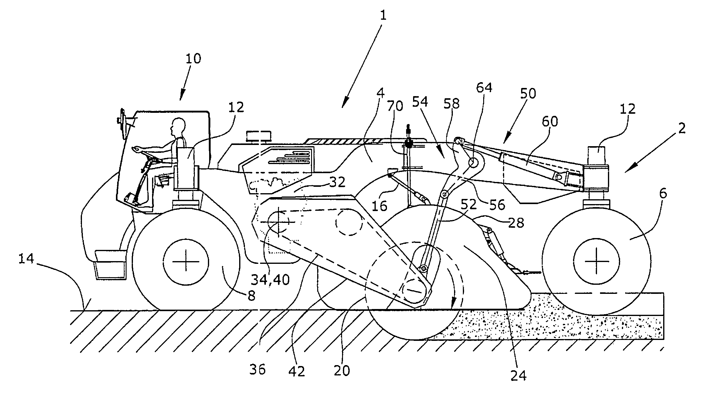
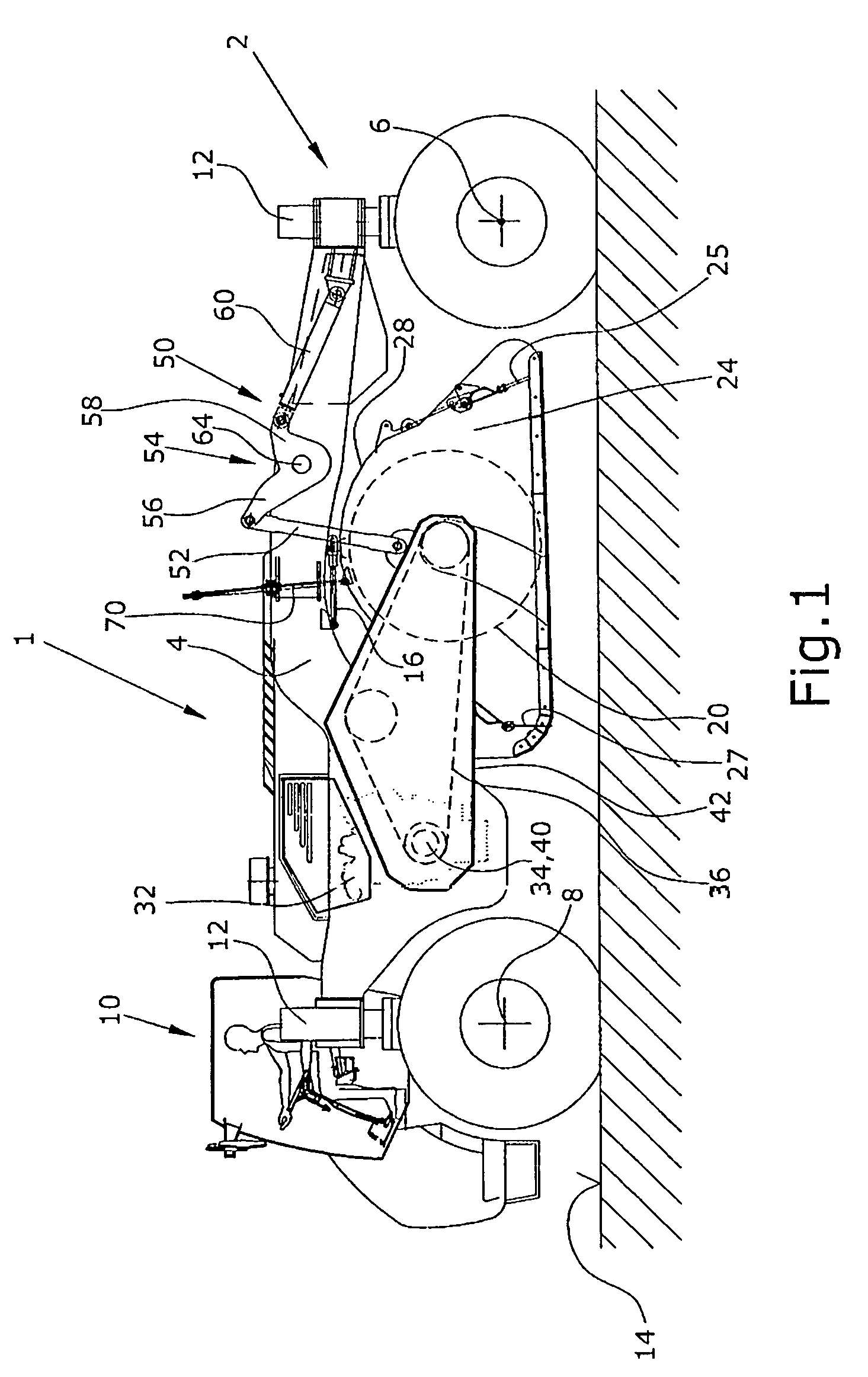
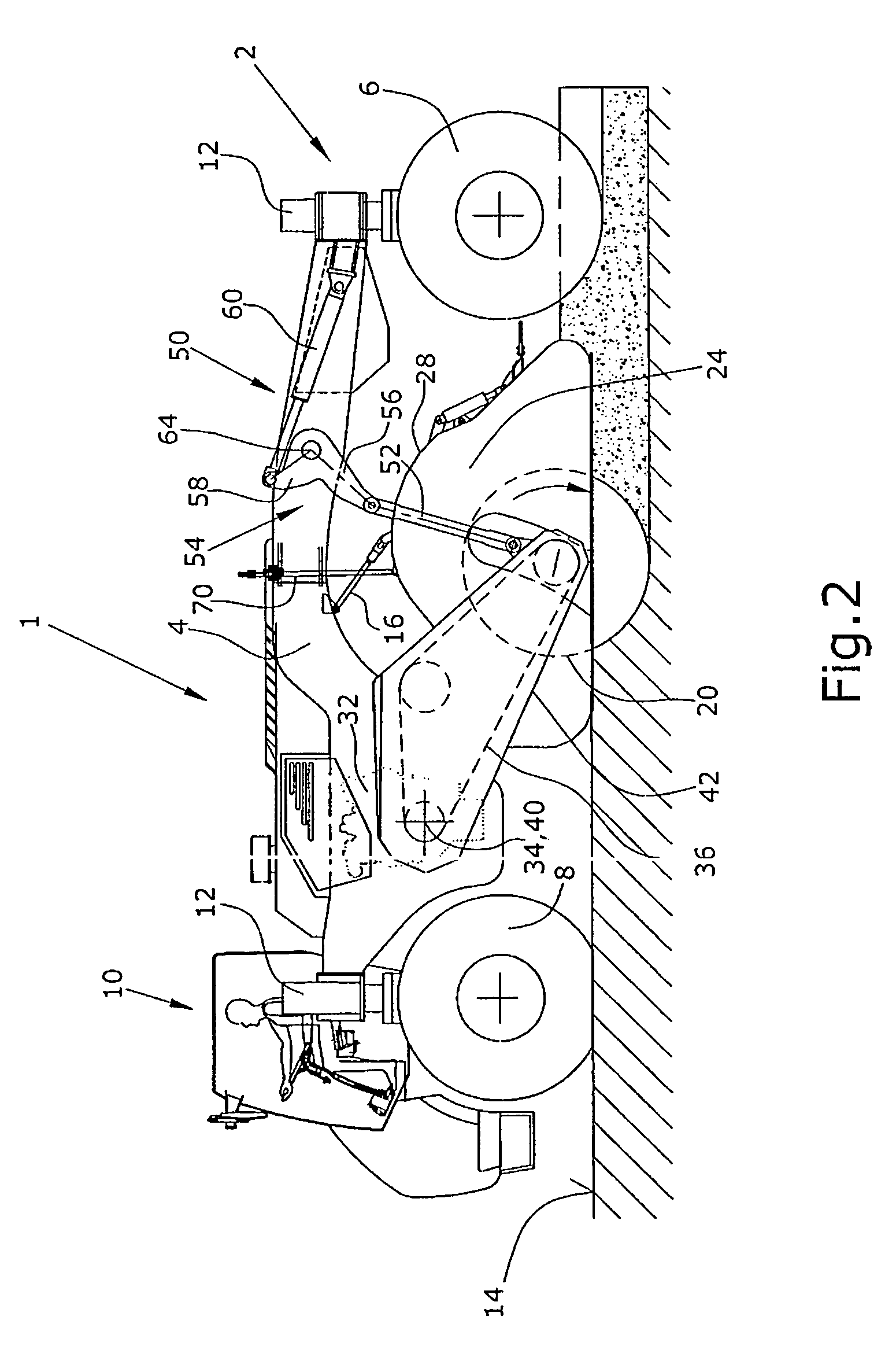
[0033]FIG. 1 shows the machine 1 for producing and working carriageways by stabilizing insufficiently stable soils or by recycling road surfaces, with a machine chassis 4 supported by a running gear 2. The running gear 2 shows two each rear and front wheels 6, 8 that are attached to lifting columns 12 in a height-adjustable manner and that can be raised and lowered independently of each other or simultaneously. It is understood that other drive means, e.g. track chains, can also be provided in lieu of the wheels 6, 8. The lifting columns 12 are attached to the machine chassis 4.

[0034]Both axles of the running gear formed by the front and rear wheels 6, 8 respectively can be steerable.

[0035]As can be seen from FIGS. 1 and 2, an operator's platform 10 for one operator is arranged at the machine chassis 4 above the front wheels 8 or in front of the front wheels 8, whereby a combustion engine 32 for the travel drive and for driving a working drum 20 is arranged behind the driver. In thi...


PUM

PropertyMeasurementUnit
distanceaaaaaaaaaa
drive poweraaaaaaaaaa
depthaaaaaaaaaa

Abstract

In an automotive machine (1) for producing carriageways by stabilizing insufficiently stable soils or by recycling road surfaces, with a machine chassis (4) supported by a running gear (2), a working drum (20) mounted to pivot in relation to the machine chassis (4), the shaft of which is mounted in pivoting arms (42) and runs transversely to the direction of travel, a cover (28) surrounding the working drum (20), a combustion engine (32) supported by the machine chassis with at least one output shaft (34) for the drive power required for driving the working drum, whereby at least one mechanical power transmission device (36) transfers the drive power from the output shaft (34) to the working drum (20), it is intended that the combustion engine (32) is arranged in a fixed manner at the machine chassis (4) between the pivoting arms (42) and that the at least one mechanical power transmission device (36), together with the working drum (20) mounted in the pivoting arms, can pivot about the axis of the output shaft (34) of the combustion engine (32).

Description

BACKGROUND OF THE INVENTION[0001]The invention relates to an automotive machine for producing carriageways. Such machines are needed for the conditioning of material, namely the stabilization of insufficiently stable soils, the pulverization of hard asphalt pavements to the recycling of bound or unbound carriageway surfaces.[0002]The known construction machines mostly show a working drum that revolves in a working chamber and is generally arranged in a height-adjustable manner for adjustment to the required milling depth and the surface to be worked. An adjustment of the slope can be effected by means of the running gear.[0003]Adapted to the particular applications, the particular processes, such as removing and crushing the milled carriageway material, adding binding agents, mixing and spreading added materials, take place in this working chamber that is confined by a cover. A detailed explanation of the tasks to be solved by such machines and of the problems occurring can be infer...

Claims


Application Information

Patent Timeline
Patent Type & Authority Patents(United States)
IPC IPC(8): E01C23/088E01C21/00E01C23/06
CPCE01C21/00E01C23/065E01C23/127E01C23/088Y10T29/49826E01C2301/30E01C23/12E01C19/46E01C23/08
Inventor MANNEBACH, THOMASBUSLEY, PETERBUHR, KARSTENHAEHN, GUENTER
Owner WIRTGEN GMBH
Why Eureka
Try Eureka