Handheld power tool with vibration-damped handle

a technology of vibration-damped handles and power tools, which is applied in the direction of percussive tools, portable tools, pivots, etc., can solve the problems of strong vibration in the tool, not only unpleasant to the user, but can even be harmful to health, so as to reduce the amount of space required, improve wear resistance, and facilitate the movement of the lever connection

Inactive Publication Date: 2011-04-12
ROBERT BOSCH GMBH
View PDF37 Cites 22 Cited by
  • Summary
  • Abstract
  • Description
  • Claims
  • Application Information

AI Technical Summary

Benefits of technology

[0005]It is proposed that each lever, between the joint region and the respective articulation point, has a bearing point. This advantageously results in an improved practical implementation of vibration damping. The handle is given linear guidance, which is economical and low in friction. A very compact design is also achieved. Because the levers are each connected to the housing or to the handle by way of only one bearing point, the handle is very strongly decoupled from tool housing vibration. Furthermore, the handle with the lever construction gains quite high stability. By the incorporation of a resilient element, effective vibration damping is attained. The user is protected against harmful and / or annoying vibration. Moreover, handling of the handheld power tool is made easier. The handheld power tool is preferably an electric power tool, in particular a drill hammer, chiseling hammer, and the like.
[0008]The levers may be braced with spring force on the handle. To that end, one, two, or more spring elements may be provided, which may be embodied either passively as conventional springs or actively in the form of suitable actuators. Expediently, it is provided that the levers are located inside the handle. This advantageously makes for a perceptible reduction in the amount of space required for the vibration damping.
[0009]In a favorable embodiment, the two levers may merge in one piece with one another. The joint region between the legs, in this embodiment, may be embodied as an elastic connection tongue. Expediently, at least one of the bearing points then makes a longitudinal compensation possible.
[0010]If the two legs of the handle, in the aforementioned joint region, are pivotably connected via a fork and a ball-like body that engages it, favorable movability of the lever connection is possible. For improved wear resistance, a sliding block may be located between the fork and the ball-like body; the ball-like body is pivotably secured to the sliding block and can slide in the fork when the ball-like body moves up and down.
[0011]It is advantageous if the handle can be braced on the housing by spring force. The handle is supported in such a way that it is extensively free of friction and it can execute a longitudinal motion in the direction of a primary vibration direction of a handheld power tool. A further advantageous embodiment for vibration damping of the handle is that one or more electrically controllable or regulatable actuators are located between the handle and the tool housing and damp vibration of the handle by counteracting a force or motion that occurs as a result of the vibration of the tool housing.

Problems solved by technology

Particularly in handheld power tools with a percussive drive, such as in drill hammers, chiseling hammers, and the like, relatively strong vibration occurs in the tool; it is transmitted to the handle of the tool and is not only unpleasant to the user but can even be harmful to health.

Method used


Image

  • Handheld power tool with vibration-damped handle
  • Handheld power tool with vibration-damped handle
  • Handheld power tool with vibration-damped handle

Examples


Embodiment Construction

[0017]Elements that remain essentially the same are identified throughout by the same reference numerals.

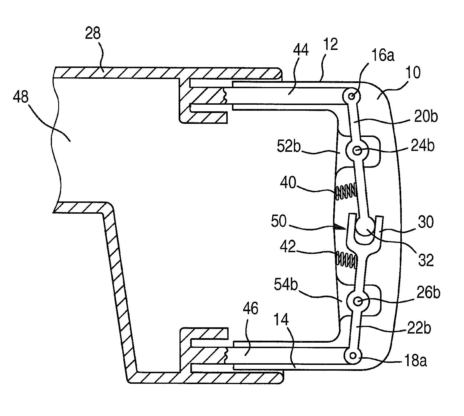
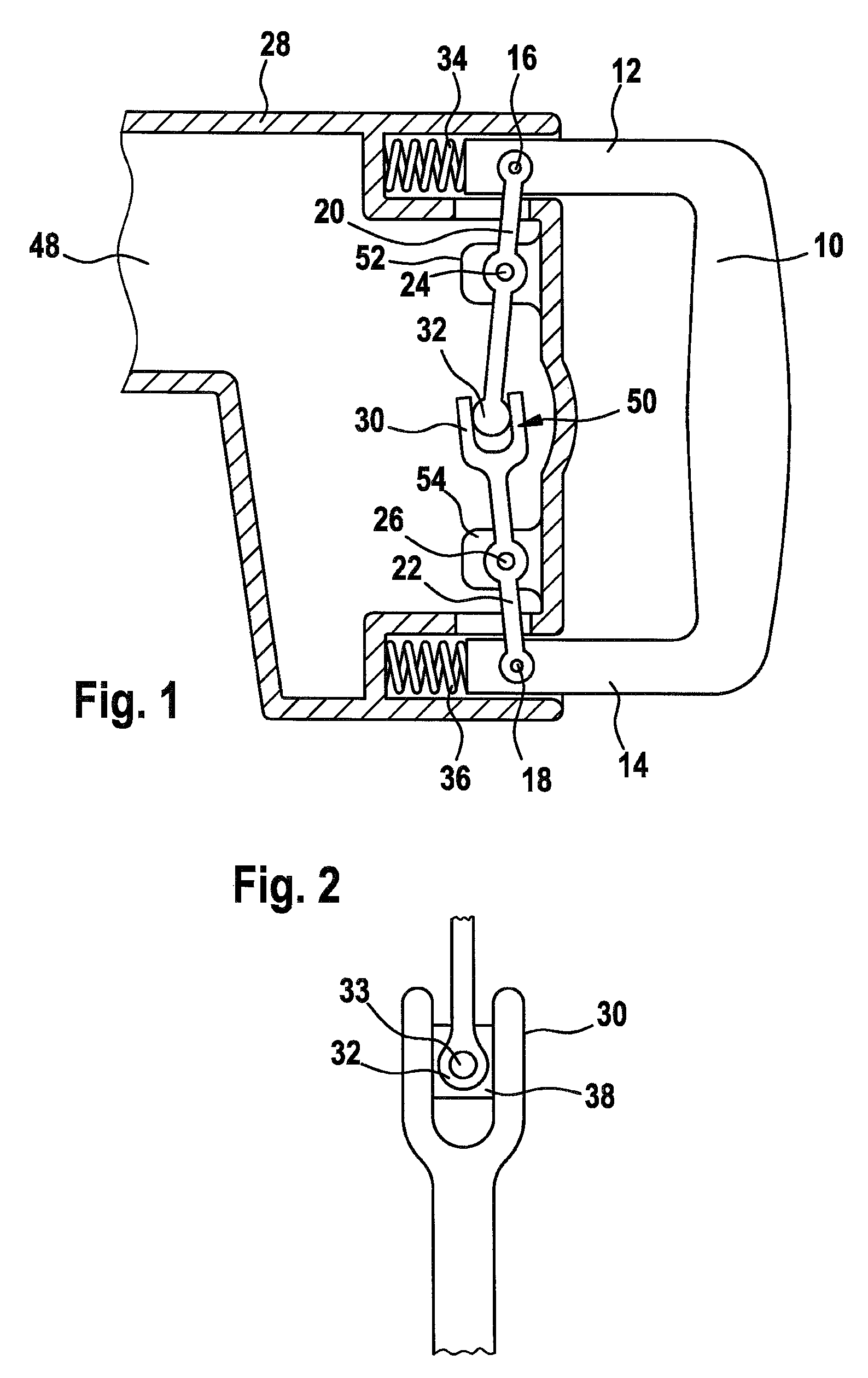
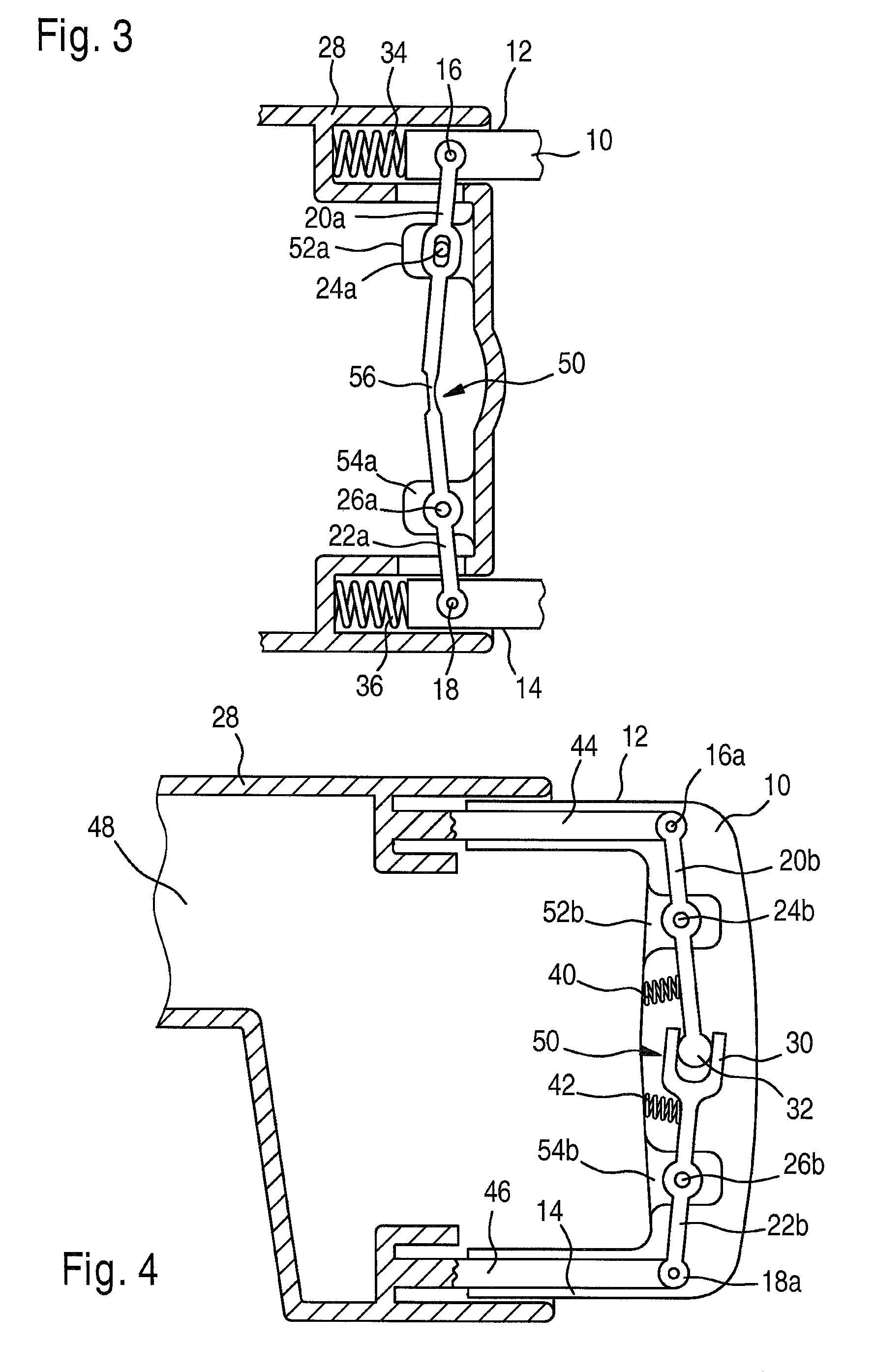
[0018]FIG. 1 shows a detail of a handheld power tool, not shown further in the drawings, with a vibration-damped handle 10 that has two legs 12, 14, extending in the longitudinal direction 48 of the handheld power tool, and that is coupled resiliently to the housing 28.

[0019]One lever 20, oriented transversely, in this case essentially perpendicular, to the longitudinal direction 48 of the handheld power tool is pivotably connected by one of its two ends to one leg 12 at a articulation point 16 and by its other end to a joint region 50 located between the legs 12 and 14 of the handle 10. Symmetrically to it, a lever 22 of the same kind is pivotably connected by one end to the other leg 14 at an articulation point 18 and is likewise pivotably connected by its other end in the joint region 50. The levers 20, 22 extend through openings, not identified by reference numeral, in the ho...


PUM


Abstract

The invention is based on a portable power tool having a vibration-damped handle (10) which has two legs (12, 14) running in the longitudinal direction (48) of the portable power tool and which is motionally coupled to its housing (28), wherein at least one lever (20, 22; 20a, 22a; 20b, 22b) oriented transversely to the longitudinal direction (48) is coupled to each of the two legs (12, 14) at an articulation point (16, 18; 16a, 18a), and wherein the levers (20, 22; 20a, 22a; 20b, 22b) are coupled to a joint region (50) lying between the two legs (12, 14) of the handle (10). It is proposed that each lever (20, 22; 20a, 22a; 20b, 22b) have a bearing point (24, 26; 24a, 20 26a; 24b, 26b) between the joint region (50) and the respective articulation point (16, 18; 16a, 18a).

Description

CROSS-REFERENCE TO RELATED APPLICATION[0001]The invention described and claimed hereinbelow is also described in German Patent Application DE 10 2006 016 442.3 filed on Apr. 7, 2006. This German Patent Application, whose subject matter is incorporated here by reference, provides the basis for a claim of priority of invention under 35 U.S.C. 119(a)-(d).BACKGROUND OF THE INVENTION[0002]Particularly in handheld power tools with a percussive drive, such as in drill hammers, chiseling hammers, and the like, relatively strong vibration occurs in the tool; it is transmitted to the handle of the tool and is not only unpleasant to the user but can even be harmful to health.[0003]From German Patent Disclosure DE 101 36 015 A1, a handheld power tool is known, having a vibration-damped handle which has two legs, extending approximately parallel to the longitudinal direction of the handheld power tool, and is coupled resiliently to the tool housing. One lever, oriented essentially perpendicular ...

Claims


Application Information

Patent Timeline
Patent Type & Authority Patents(United States)
IPC IPC(8): B25D17/00
CPCB25D17/043Y10T403/32631B25D2250/371B25D2250/085
Inventor ENGELFRIED, UWESCHMID, LARSSCHNITZLER, JOHANNESMEIXNER, GERHARDLENNARTZ, JUERGENKOALICK, JAN
Owner ROBERT BOSCH GMBH
Why Eureka
Try Eureka