Security lock for a sash type window

a security lock and window technology, applied in the field of window locks, can solve the problems of obstructing the intended function of the window, and expensive window reinforcements, locks and other means to prevent entry,

Active Publication Date: 2011-04-12
LAWRENCE BARRY G
View PDF25 Cites 42 Cited by
  • Summary
  • Abstract
  • Description
  • Claims
  • Application Information

AI Technical Summary

Benefits of technology

[0007]It is another objective of the present invention to provide a sash type window lock which is handle-operated as with a conventional lock, yet which provides added security,
[0010]The aforesaid and other objectives are realized by providing a lock formed from a plastic composite material, or a metal such as zinc, aluminum or other suitable materials. The preferred form of the lock includes a handle, housing, cam and keeper formed form a standard zinc die-cast material having added security for use on sash type windows and the like. The housing includes an indent with a pair of guide portions. The cam is positioned within the indent and includes an axle port, the axle port having a semi-circular shaped axle port outer wall. A shaft of an axle is adapted to be inserted into the axle port so that the cam and the axle are rotatable together. The cam includes a sweep arm and a channel disposed on an upper surface of the sweep arm. The sweep arm of the cam has an outer wall that is either elongate-shaped or semicircular-shaped. On the other hand, the channel on the upper surface of the sweep arm is bounded on one side by the axle port outer wall and bounded on an opposite side by an elongated-arcuate portion of the inner wall of the sweep arm. The elongated-arcuate portion of the inner wall of the sweep arm allows the security lock to be self locating when the keeper and the housing are misaligned when installed, respectively, on upper and lower sashes of the window.
[0011]The housing also includes a groove that is substantially circular-shaped, the groove having an indentation on a wall of the groove. A resilient tension member is disposed in the circular-shaped groove and is rotatable by the axle. The tension member includes at least one projection for engaging with the indentation on the wall of the groove when the axle is rotated to a predetermined position. Upon rotation of the axle, the cam rotates about the guide portions, the projection of the tension member engages with indentation of the groove wall, and the lock is placed into a locked posture. As the cam rotates, a terminal end of the channel of the cam prevents further circular rotation. At the same time, the rotation of the cam causes the cam channel to engulf a keeper catch positioned on an opposing window sashes. As mentioned above, the elongated-arcuate portion of the inner wall of the sweep arm allows the security lock to be self-locating when the keeper and the housing are misaligned when installed, respectively, on upper and lower sashes of the window.

Problems solved by technology

However, adding locking devices tends to inconvenience the home or business owner and obstructs the intended function of the window.
Window reinforcements, locks and other means to prevent entry are often expensive, inconvenient and are often difficult to use and require extra thought, time and effort by the owner.
Sometimes these other means to prevent entry are installed, and when not installed, conventional locks provide little if any protection against unauthorized entry.

Method used


Image

  • Security lock for a sash type window
  • Security lock for a sash type window
  • Security lock for a sash type window

Examples


Embodiment Construction

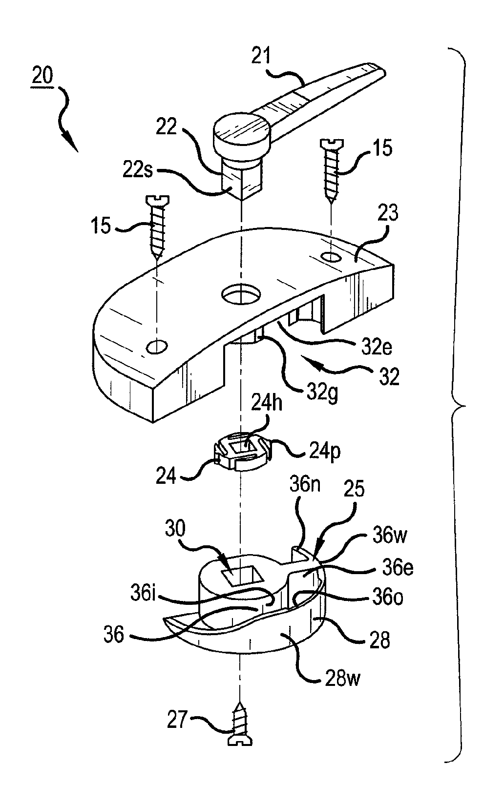
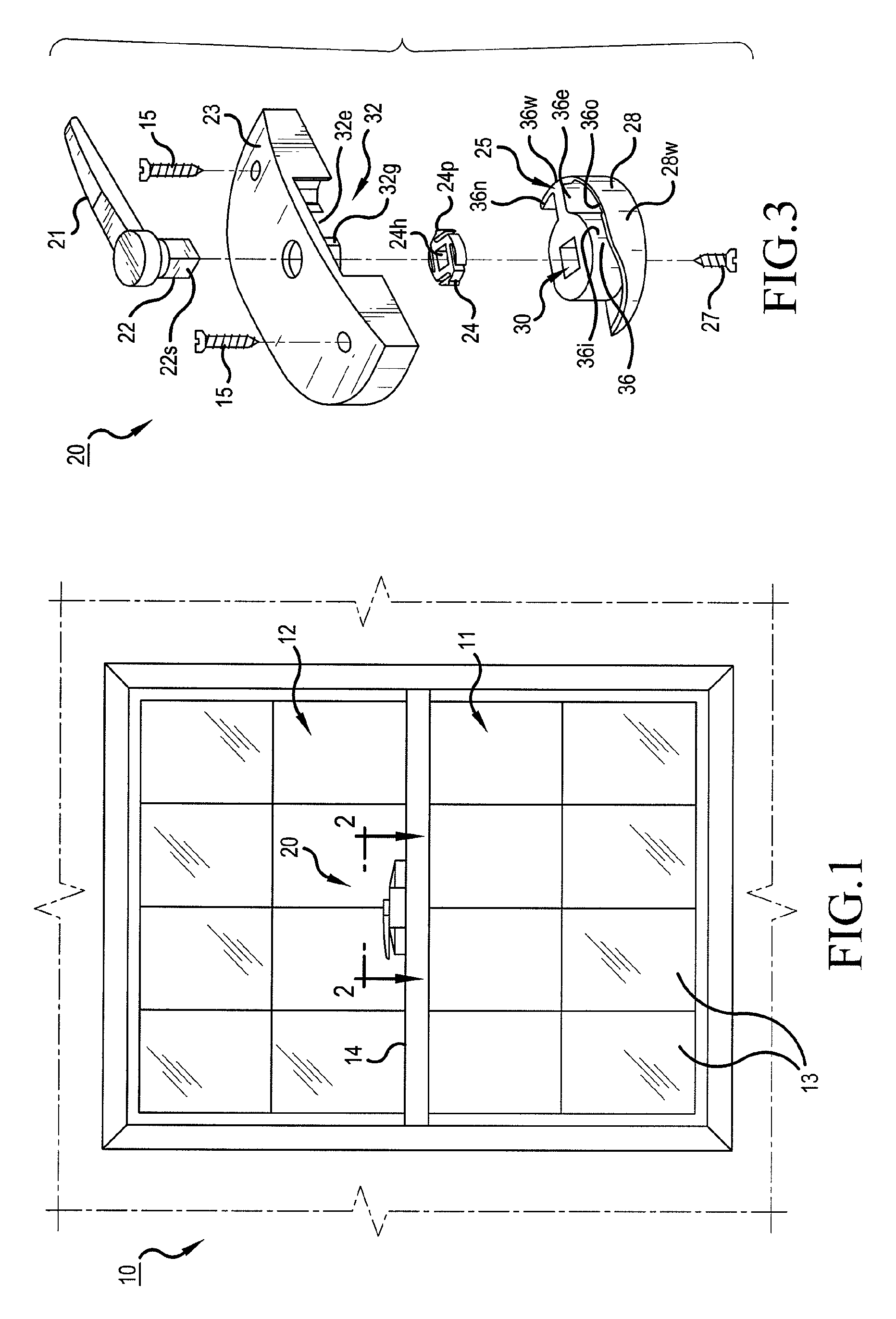
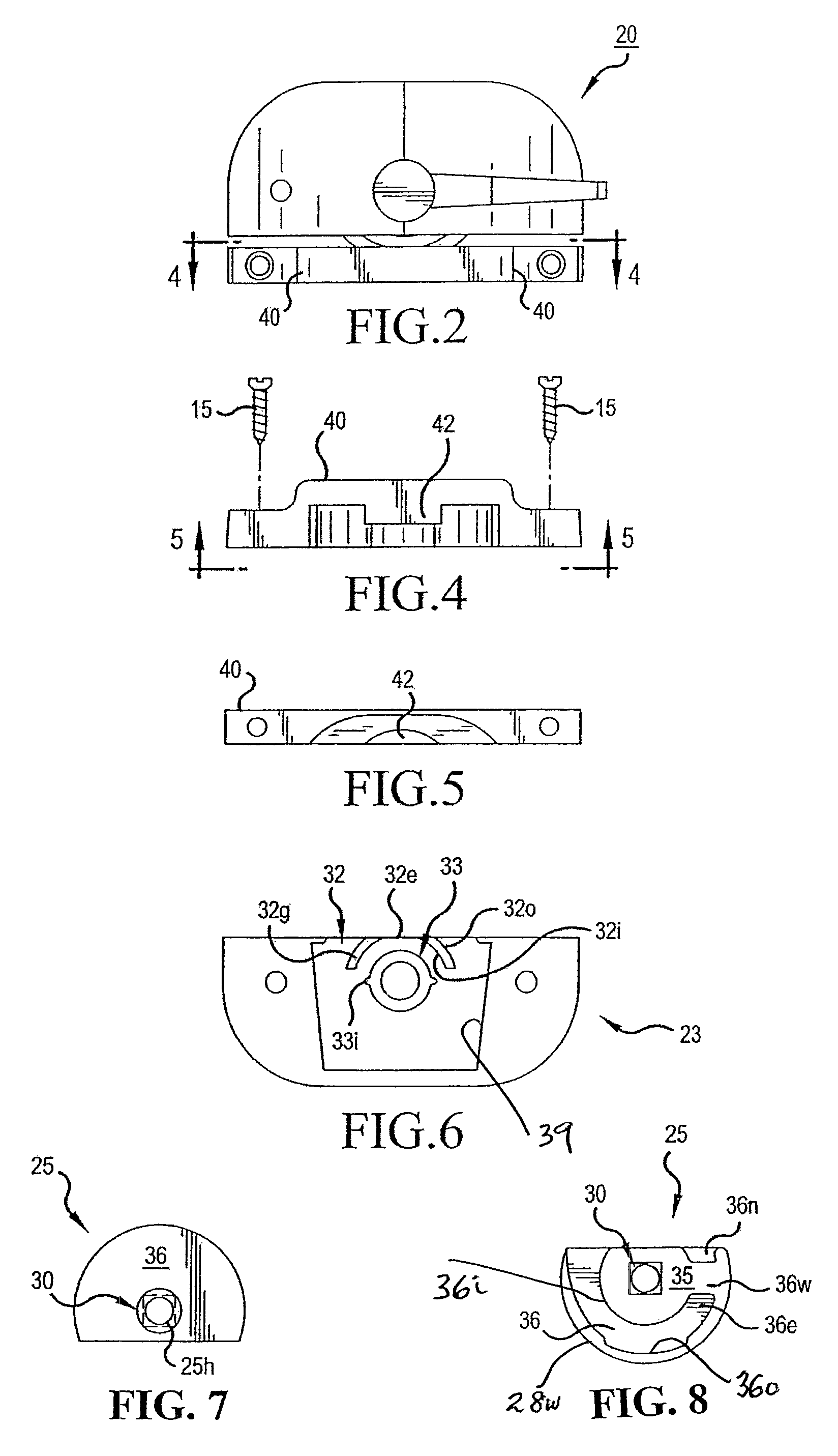
[0027]For a better understanding of the invention and its operation, turning now to the drawings, FIG. 1 illustrates in schematic fashion a typical sash window 10 as used in homes and other buildings. Window 10 includes lower movable sash 11 having eight (8) glass panes 13 and top rail 14. Upper sash 12 may be movable or fixed and includes a bottom rail (not shown) which is coplanar with top rail 14 of sash 11 when window 10 is fully closed as seen in FIG. 1. Preferred sash lock 20 formed from a standard zinc die-cast material is shown mounted to top rail 14 of sash 11, and as would be understood, a keeper such as conventional keeper 40 (FIG. 4, for example) is mounted to the bottom rail (not shown) of upper sash 12 and is aligned for engagement with lock 20. Lock 20 may also be formed from a standard nylon / fiberglass composite material if desired. Lock 20 and keeper 40 are affixed to window 10 as by conventional screws 15 seen in FIGS. 3 and 4, although other suitable attachment me...


PUM


Abstract

A security lock having a housing and a cam. The housing includes an indent with a pair of guide portions. The cam is positioned within the indent and includes an axle port. A shaft of an axle is adapted to be inserted into the axle port so that the cam and the axle are rotatable together. The cam includes a sweep arm and a channel disposed on an upper surface of the sweep arm. The sweep arm has an outer wall that is either elongate-shaped or semicircular-shaped. The channel has a semi-circular-shaped inner wall and an elongate-shaped outer wall. Upon rotation of the axle, the cam rotates about the guide portions into a locked posture in the housing. The elongate-shaped outer wall of the channel allows the security lock to be self-locating when the housing and a keeper are misaligned when installed, respectively, on opposing window sashes.

Description

BACKGROUND OF THE INVENTION[0001]1. Field of the Invention[0002]The invention herein pertains to window locks and the like and particularly pertains to a security lock for a window sash. The cam of the security lock includes a sweep arm channel having an elongate-shaped outer wall for engaging a keeper.[0003]2. Description of Background Art[0004]In recent years, burglars have become adapt at opening sash type windows from the outside of a house or other building by first removing the window screen and placing a putty knife or similar thin bladed instrument between the sashes to rotate the cam to an unlocked posture. The blade is used by unauthorized persons to urge the rotatable cam to disengage the cam from the keeper. Once the cam has been disengaged, the sash is then openable for entry purposes. Attempts have been made to secure such windows such as by use of extra locks or by drilling holes in the sash and window frame and inserting nails or steel rods therein for immobilization...

Claims


Application Information

Patent Timeline
Patent Type & Authority Patents(United States)
IPC IPC(8): E05C3/04E05C3/14
CPCE05B65/0841E05C3/046E05C2007/007Y10S292/20Y10S292/47Y10T292/1041Y10T292/104Y10T70/515
Inventor LAWRENCE, BARRY G.
Owner LAWRENCE BARRY G
Why Eureka
Try Eureka