Removable polyaxial housing for a pedicle screw

a technology of pedicle screw and polyaxial housing, which is applied in the field of spine fixation devices, can solve the problems of significantly more difficult reanimation of the polyaxial screw, if possible at all

Inactive Publication Date: 2011-04-12
ZIMMER BIOMET SPINE INC
View PDF37 Cites 112 Cited by
  • Summary
  • Abstract
  • Description
  • Claims
  • Application Information

AI Technical Summary

Benefits of technology

[0011]This invention addresses these and other shortcomings in the prior art. In one embodiment, the invention is a polyaxial pedicle screw with a polyaxial body which is selectively removable from the screw in a spinal fixation system without disruption of the screw's placement in the patient's spine. The polyaxial body according to various embodiments of this invention may be locked relative to the screw head and coupled to the spine rod without deformation of the screw or body components while still allowing for subsequent removal of the body from the screw head.
[0012]The removable polyaxial screw in one embodiment has a threaded shaft that is inserted into a selected vertebra of a patient. The pedicle screw also has a head with a convex portion that, in one embodiment, includes a thread extending entirely around the convex portion of the screw head. A polyaxial body is selectively engaged with the screw head and includes a U-shaped channel in which the spine rod is captured by a set screw seated in the polyaxial body. The polyaxial body and pedicle screw allow for a variety of different configurations to accommodate various patient and spine rod geometries thereby providing the polyaxial benefits associated with polyaxial pedicle screws during the installation and design of the spinal fixation system. The pedicle screw and the polyaxial body lock to each other when the spine rod is clamped by a set screw in the U-shaped channel without crimping or deforming any of the components.
[0013]In one embodiment, the head of the pedicle screw is threadably engaged with a retainer ring on the polyaxial body thereby permitting selective removal of the body from the screw head without disrupting the placement of the screw in the spine. This allows for the pedicle screw to remain in the spine as the fixation system is adjusted as required by the surgeon. The advantages of the ability to remove the polyaxial body from the polyaxial pedicle screw include reduced inventory, greater surgical work area and ease of insertion and alteration of the types of polyaxial constructs available to the surgeon when treating the patient.
[0014]The removable polyaxial pedicle screw of this invention allows for the relative motion between the polyaxial body and the pedicle screw to be locked when the spine rod is coupled thereto. The locking mechanism does not involve deformation, swaging, crimping or other mutilation of the polyaxial housing and screw components. Other locking mechanisms utilize deformation of a component or wedging a component against another and such approaches make reanimation of the polyaxial screw significantly more difficult, if possible at all.
[0015]The ability to remove the body from the installed screw offers significant benefits to the surgeon and patient. The threaded engagement between the polyaxial screw head and the polyaxial body allows for the body to be removed, replaced, adjusted and / or reattached to the screw and polyaxial construct as needed. As such, the pedicle screw insertion is not restricted by the geometry or mechanics of the polyaxial construct. Reduction in inventory is realized because a wide variety of screw configurations can be built from a few components. As an example, if five pedicle screw lengths of a specific diameter and four polyaxial body assemblies are required for a fixation system, then a total of 20 screws are currently required. With this invention, the same fixation system requirements would be satisfied with only nine components (four polyaxial bodies and five pedicle screws) thereby significantly reducing the inventory requirements for spinal fixation systems.

Problems solved by technology

Other locking mechanisms utilize deformation of a component or wedging a component against another and such approaches make reanimation of the polyaxial screw significantly more difficult, if possible at all.

Method used


Image

  • Removable polyaxial housing for a pedicle screw
  • Removable polyaxial housing for a pedicle screw
  • Removable polyaxial housing for a pedicle screw

Examples


Embodiment Construction

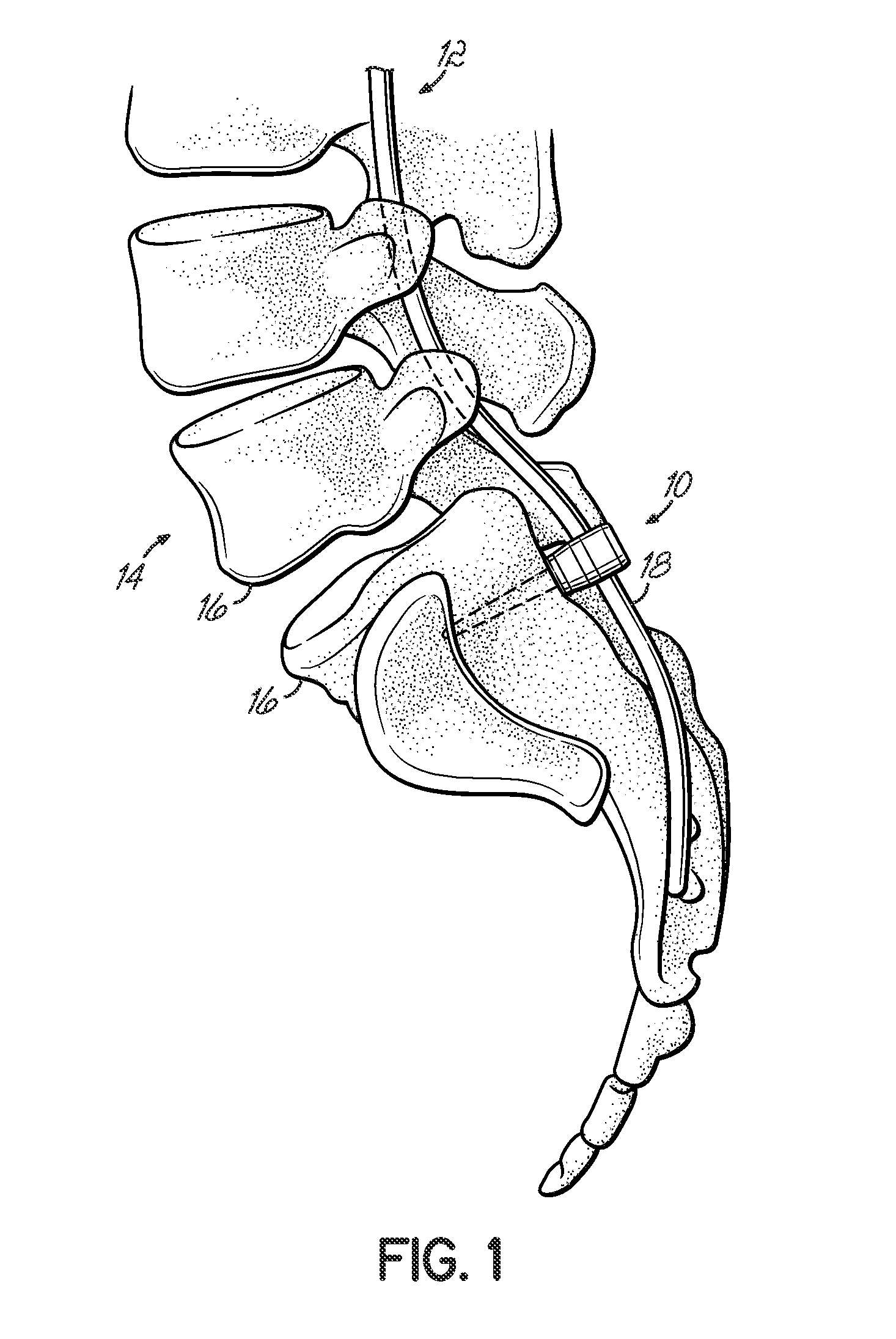
[0022]Referring to FIG. 1, one embodiment of a removable polyaxial pedicle screw assembly 10 is shown as part of a spinal fixation system 12 mounted to a spine 14 of a patient. The pedicle screw assembly 10 is shown inserted into a vertebra 16 in the sacrum of the patient's spine 14 with a spine rod 18 mounted to the pedicle screw assembly 10. However, it will readily be appreciated by those of ordinary skill in the art that the pedicle screw of this invention can readily be used at other locations along the spine or other bones in a patient's body in addition to those shown in FIG. 1.

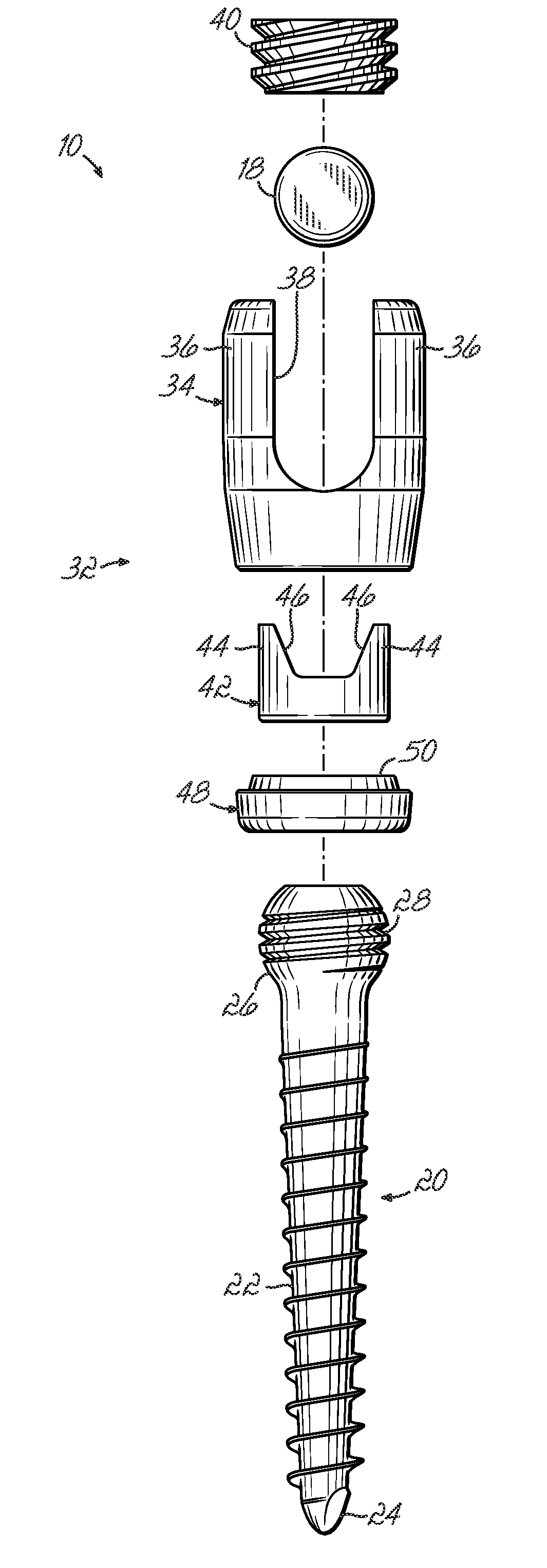
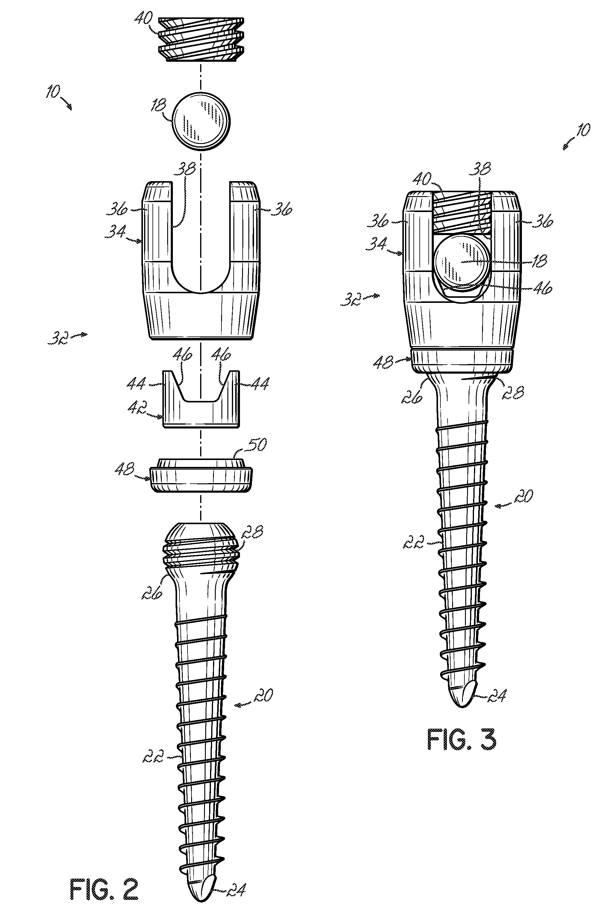
[0023]As shown in FIG. 2, the pedicle screw assembly10 according to one embodiment of this invention includes a pedicle screw 20 having a threaded shaft 22 and a tip 24 for insertion into the spine 14. A head 26 of the screw 20 is located opposite from the tip 24 and includes a generally spherical or convex profile with a helical thread 28 extending circumferentially around the screw head 26. The pedic...


PUM


Abstract

A polyaxial body is selectively removable from a pedicle screw in a spinal fixation system without disruption of the screw's placement in the patient's spine. The polyaxial body according to various embodiments of this invention may be locked relative to the screw head and coupled to the spine rod without deformation of the screw or body components while still allowing for subsequent removal of the body from the screw head. The head of the pedicle screw is threadably engaged with a retainer ring on the polyaxial body thereby permitting selective removal of the body from the screw head without disrupting the placement of the screw in the spine. This allows for the pedicle screw to remain in the spine as the fixation system is adjusted as required by the surgeon for subsequent and reliable reanimation.

Description

TECHNICAL FIELD[0001]This invention relates generally to spinal fixation devices and more specifically relates to a polyaxial pedicle screw assembly with removable components.BACKGROUND[0002]The human spinal cord is a highly complex system of bones and connective tissues that provide support for the body and protect the delicate spinal column and nerves. The spinal column includes a series of vertebrae stacked one atop the other. Each vertebral body includes a relatively strong cortical bone portion forming the outside surface of the body and a relatively weak cancellous bone portion forming the center of the body. An intervertebral disc is situated between each vertebral body that provides for cushioning and dampening of compressive forces applied to the spinal column. The vertebral canal containing the delicate spinal cord and nerves is located just posterior to the vertebral bodies.[0003]Various types of spinal column disorders include scoliosis (abnormal lateral curvature of the...

Claims


Application Information

Patent Timeline
Patent Type & Authority Patents(United States)
IPC IPC(8): A61B17/70A61B17/86
CPCA61B17/7037A61B17/7032
Inventor HOFFMAN, ZACHARY M.
Owner ZIMMER BIOMET SPINE INC
Why Eureka
Try Eureka