Method for aligning a prosthesis

a prosthesis and alignment technology, applied in the field of methods for aligning prostheses, can solve the problems of inconvenient and inconvenient practice of prosthesis alignment, little progress has been made in giving a prosthetist the tools needed to optimize this aspect of prosthetic care, and inconsistent practi

Active Publication Date: 2011-04-12
ORTHOCARE INNOVATIONS LLC
View PDF31 Cites 9 Cited by
  • Summary
  • Abstract
  • Description
  • Claims
  • Application Information

AI Technical Summary

Benefits of technology

The computerized prosthesis alignment system includes a transducer that can measure the socket reactions in the anterior / posterior plane and the right / left planes, while canceling or reducing the transverse forces on the measurements of these socket reactions. In addition, the transducer is also capable of determining the axial load or weight experienced by the prosthesis.

Problems solved by technology

The importance of alignment has been recognized for many decades, but little progress has been made to give a prosthetist the tools needed to optimize this aspect of prosthetic care.
Until now, prosthesis alignment has been an imprecise and inconsistent practice based primarily on the subjective opinion and the experience of the prosthetist to visually determine the proper alignment.

Method used


Image

  • Method for aligning a prosthesis
  • Method for aligning a prosthesis
  • Method for aligning a prosthesis

Examples


Embodiment Construction

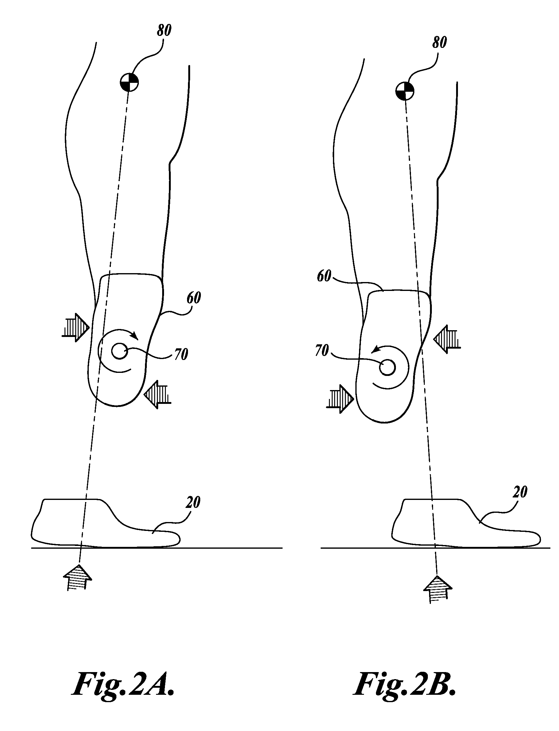
FIGS. 2A, 2B, 3A, and 3B are intended to illustrate the moments experienced at the prosthesis socket 60 that affect the comfort and function of the prosthesis. Moments are induced at the socket 60, generally when there are unbalanced forces acting on opposite sides of a theoretical reference point 70 of the socket 60. For example, the more the foot 20 is behind the center of rotation 70, the more that a clockwise moment in the anterior / posterior plane is experienced at the socket 60. On the other hand, if the foot 20 is moved forward of the reference point 70, a counterclockwise moment in the anterior / posterior plane is experienced at the socket 60. Similar forces can be experienced in the right / left plane.

For example, referring to FIGS. 3A and 3B, the more the foot 20 is moved to the left of the reference point 70, the more a counterclockwise moment in the right / left plane is experienced at the socket 60. On the other hand, if the foot 20 is moved to the right of the reference poin...


PUM


Abstract

A computerized prosthesis alignment system includes a transducer that can measure socket reactions in the anterior / posterior plane and the right / left planes, while canceling or reducing the transverse forces on the measurements of these socket reactions. In addition, the transducer is also capable of determining the axial load or weight experienced by the prosthesis. The computerized prosthesis alignment system is in communication with a host computer. The moment data from the transducer is interpreted by the user via a computer interface. The host computer includes memory for storing one or more applications. These applications receive data from the transducer, interpret the data with discrete algebraic or fuzzy logic algorithms, and display the output numerically and graphically. Applications may also interpret the data to provide analyses to the user for aligning the prosthesis.

Description

BACKGROUNDAlignment of a prosthesis is an important element of optimizing its function. FIG. 1 illustrates a representative prosthesis for a transtibial amputee. The prosthesis 10 includes a foot portion 20 rigidly, but adjustably, affixed to a pylon 30. The pylon 30, in turn, is connected to the prosthesis socket 60 via a tube clamp adaptor 40 and a pyramid adaptor 50. The connection between the tube clamp adaptor 40 and the prosthesis socket 60 is adjustable to fix the alignment. Although not shown, the tube clamp adaptor 40 has an concave spherical, load-bearing surface on the upper end of the tube clamp adaptor 40. This surface includes a central hole through which the tube clamp adaptor 40 receives the pyramid adaptor 50. The pyramid adaptor 50 is so named because of the inverted pyramid-shaped protuberance that fits into the central hole of the surface in the tube clamp adaptor 40. The pyramid adaptor 50 has a convex spherical load-bearing surface designed to be supported by t...

Claims


Application Information

Patent Timeline
Patent Type & Authority Patents(United States)
IPC IPC(8): A61F2/74
CPCA61F2/60A61F2/68A61F2/76G01L5/162G01L1/2218G01L1/2231A61F2002/5023A61F2002/704A61F2002/7635A61F2002/7645A61F2002/7695A61F2002/705A61F2/66A61F2/70A61F2002/5021G01B21/24G06F30/17
Inventor MACOMBER, BEN GILBERTBOONE, DAVID ALAN
Owner ORTHOCARE INNOVATIONS LLC
Why Eureka
Try Eureka