Drop dispenser device

a dispenser device and dispenser technology, applied in the direction of diaphragms, fluid pressure measurement by electric/magnetic elements, positive displacement liquid engines, etc., can solve the problem of inability to reliably reproduce the action, and achieve the effect of minimising dependence in relation

Active Publication Date: 2011-04-12
COMMISSARIAT A LENERGIE ATOMIQUE ET AUX ENERGIES ALTERNATIVES
View PDF12 Cites 94 Cited by
  • Summary
  • Abstract
  • Description
  • Claims
  • Application Information

AI Technical Summary

Benefits of technology

[0055]One of the drop-forming electrodes advantageously has a rounded shape on one side and pointed on the other, thus favouring the drop ejection mechanism and minimising dependence in relation to the nature of the liquids and to the operating parameters of the device.

Problems solved by technology

The drawback of this method is that the action cannot be reproduced reliably.

Method used


Image

  • Drop dispenser device
  • Drop dispenser device
  • Drop dispenser device

Examples


Embodiment Construction

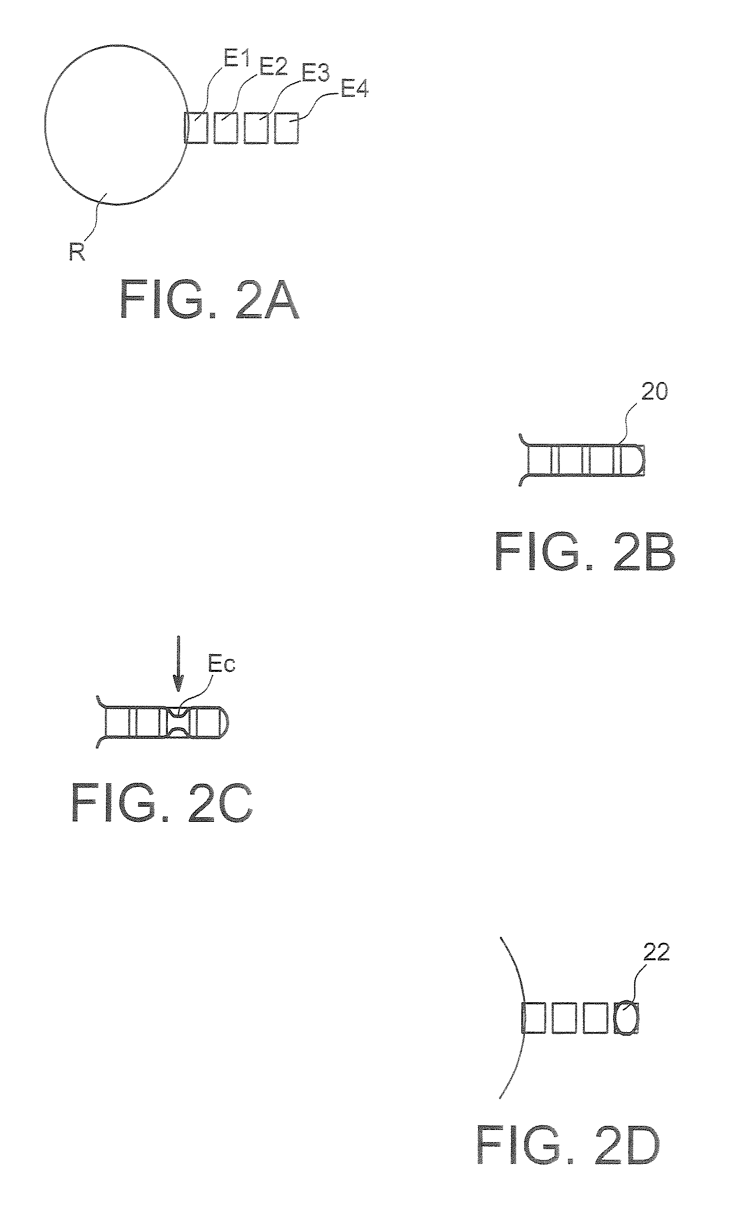
[0073]A first embodiment of the invention is illustrated in FIGS. 4A and 4D, in a top view and a side view respectively.

[0074]FIG. 4A in fact represents only the system of electrodes implemented in a calibrated drop dispensing device according to the invention.

[0075]Furthest to the left, this figure firstly shows a well 40, which is in fact created in the cover area 42 of the device (see FIG. 4B).

[0076]This well is placed at least partially in front of a transfer electrode 44, which is in fact formed in the substrate 46 of the device.

[0077]Following on from this transfer electrode is a reservoir electrode 48, which will be used to form a liquid retention micro-reservoir.

[0078]Then come drop-forming electrodes, with four formation electrodes 50, 52, 54, 56 being represented in FIGS. 4A and 4B.

[0079]A counter-electrode 47 is placed in the cover area 42.

[0080]The invention therefore proposes the organisation of a series of electrodes in a drop dispensing device, these electrodes having...


PUM

PropertyMeasurementUnit
heightaaaaaaaaaa
heightaaaaaaaaaa
heightaaaaaaaaaa

Abstract

A liquid dispensing device includes first and second substrates, with the first substrate including an opening for introduction of a fluid, and the second substrate including a multiplicity of electrodes. The device includes a transfer electrode, located at least partially opposite to the opening, at least two drop-forming electrodes, and a reservoir electrode, located between the transfer electrode and the drop-forming electrodes, and with an area that is at least equal to three times the area of each drop-forming electrode.

Description

[0001]This application is a 371 of PCT / FR2005 / 051131 filed on Dec. 22, 2005, which claims foreign priority from French application 0453211, filed on Dec. 23, 2004.TECHNICAL AREA AND PRIOR ART[0002]The invention concerns a device and a process for the formation of drops or of small volumes of liquid, from a liquid reservoir, using electrostatic forces.[0003]In particular, the invention concerns a liquid dispensing device that can be applied in discrete microfluidics, or drop microfluidics, with a view to chemical or biological applications for example.[0004]The invention applies to the formation of drops in devices, with a view to biochemical, chemical or biological analyses, whether in the medical area, in environmental surveillance, or in the area of quality control.[0005]One of the most frequently used methods of fluid movement or manipulation is based upon the principle of electro-wetting on a dielectric, as described in the article by M. G. Pollack, A. D. Shendorov, and R. B. Fa...

Claims


Application Information

Patent Timeline
Patent Type & Authority Patents(United States)
IPC IPC(8): G01N27/453G01N27/447
CPCB01L3/502792F04B19/006B01L3/0241B01L2200/0605B01L2300/089B01L2400/0427B01L2300/0816
Inventor FOUILLET, YVESJARY, DOROTHEE
Owner COMMISSARIAT A LENERGIE ATOMIQUE ET AUX ENERGIES ALTERNATIVES
Why Eureka
Try Eureka