
Communication apparatus, image sensing apparatus, and control method therefor

a technology of image sensing apparatus and communication apparatus, which is applied in the direction of transmission, television system, instruments, etc., to achieve the effect of preventing a data transfer between the devices and minimizing the period of tim

Inactive Publication Date: 2011-04-12
CANON KK
View PDF20 Cites 16 Cited by
  • Summary
  • Abstract
  • Description
  • Claims
  • Application Information

AI Technical Summary

Benefits of technology

[0018]Another object of the present invention, for example, is to provide a technique for preventing a data transfer between the devices from interruption caused when a DHCP server suddenly leaves an UPnP network, and minimizing the period of time in which the devices cannot exchange data, caused by the difference between the address setting change timings of the devices.

Problems solved by technology

However, in the network where the IP addresses of the plurality of UPnP devices are managed by the DHCP server, a problem to be described below occurs if the DHCP server leaves the network.

Method used


Image

  • Communication apparatus, image sensing apparatus, and control method therefor
  • Communication apparatus, image sensing apparatus, and control method therefor
  • Communication apparatus, image sensing apparatus, and control method therefor

Examples


first embodiment

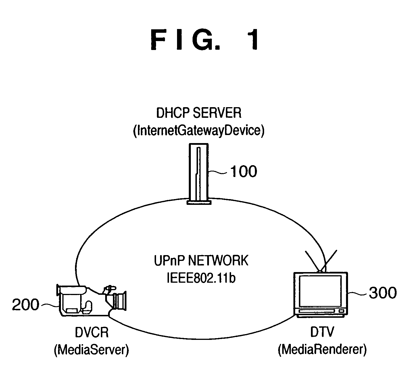
[0034]FIG. 1 is a view showing the example of an UPnP network arrangement. A digital video camcoder (to be referred to as a DVCR hereinafter) 200 is a device which functions as a MediaServer defined by the Audio Video Working Committee (AVWC). A digital television (to be referred to as a DTV) 300 is a device which functions as a MediaRenderer also defined by the AVWC. A DHCP server 100 is an InternetGatewayDevice defined by the InternetGateway WC. The DTV 300 also functions as the control point of UPnP. All of the devices are connected with a wireless interface which is based on the IEEE802.b. Note that the DHCP server 100 in the first embodiment is implemented by an access point which is based on the IEEE802.b. Each of the DVCR 200 and DTV 300 functions as a DHCP client and AutoIP.

[0035]In the first embodiment, the present invention is applied to the DVCR 200. Note that the present invention can also be applied to an apparatus (e.g., digital camera, cellular phone, or mobile comput...

second embodiment

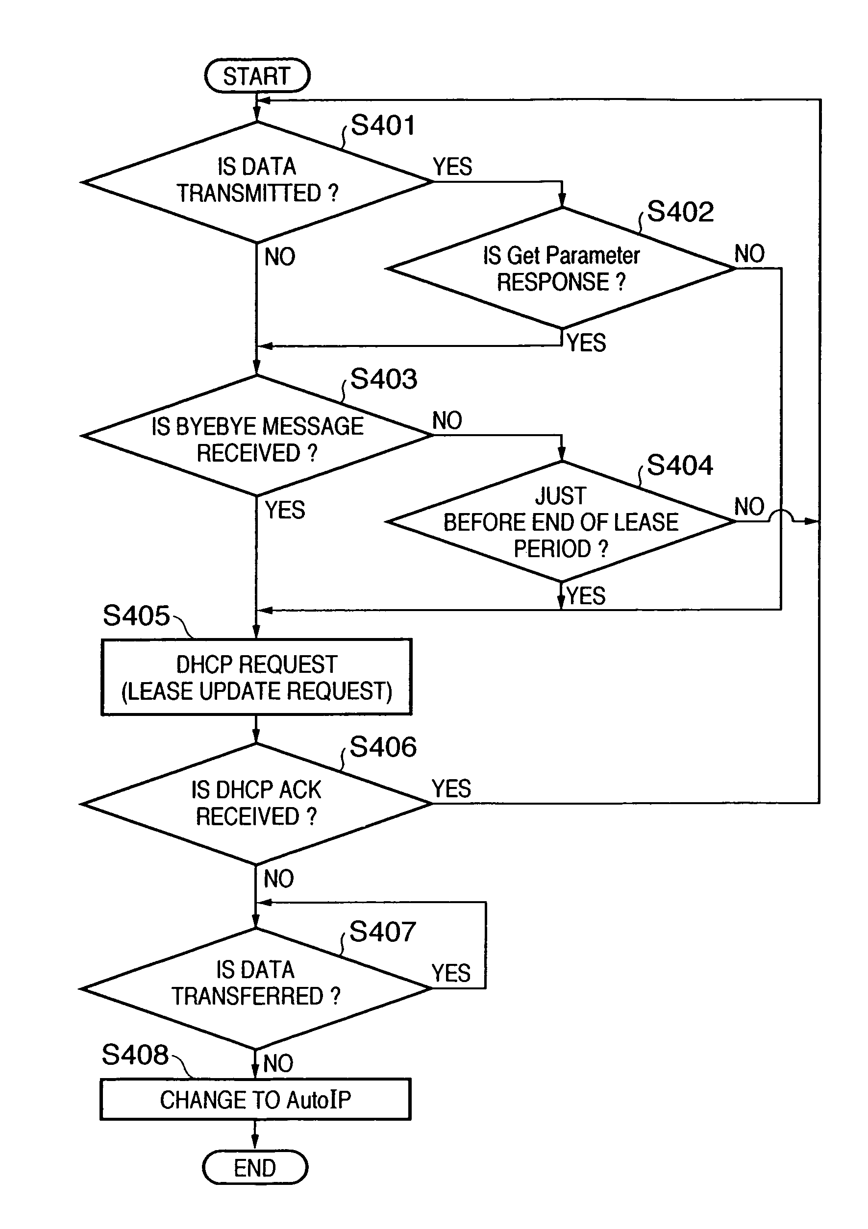
[0053]In the second embodiment, the timing to check whether a DHCP server 100 leaves a network is improved. For the sake of simplicity, a network arrangement in the second embodiment is same as that in FIG. 1, and the present invention is applied to a DVCR 200.

[0054]The DVCR 200 in the second embodiment is processed in accordance with the flowchart in FIG. 4 from when an IP address is assigned by the DHCP server 100 until the DHCP server 100 shifts to AutoIP after leaving an UPnP network.

[0055]First, the DVCR 200 determines whether the data is transferred to another device on the network (step S401). In this embodiment, the DVCR 200 determines whether an RTP / RTSP transfer is performed. If YES in step S401, the DVCR 200 constantly confirms the connection with a connection partner (a DTV 300 in this embodiment) by using a GET PARAMETER command of RTSP in step S402 (step S402). When the confirmation response cannot be received from the connection partner to this request, the DVCR 200 i...


PUM


Abstract

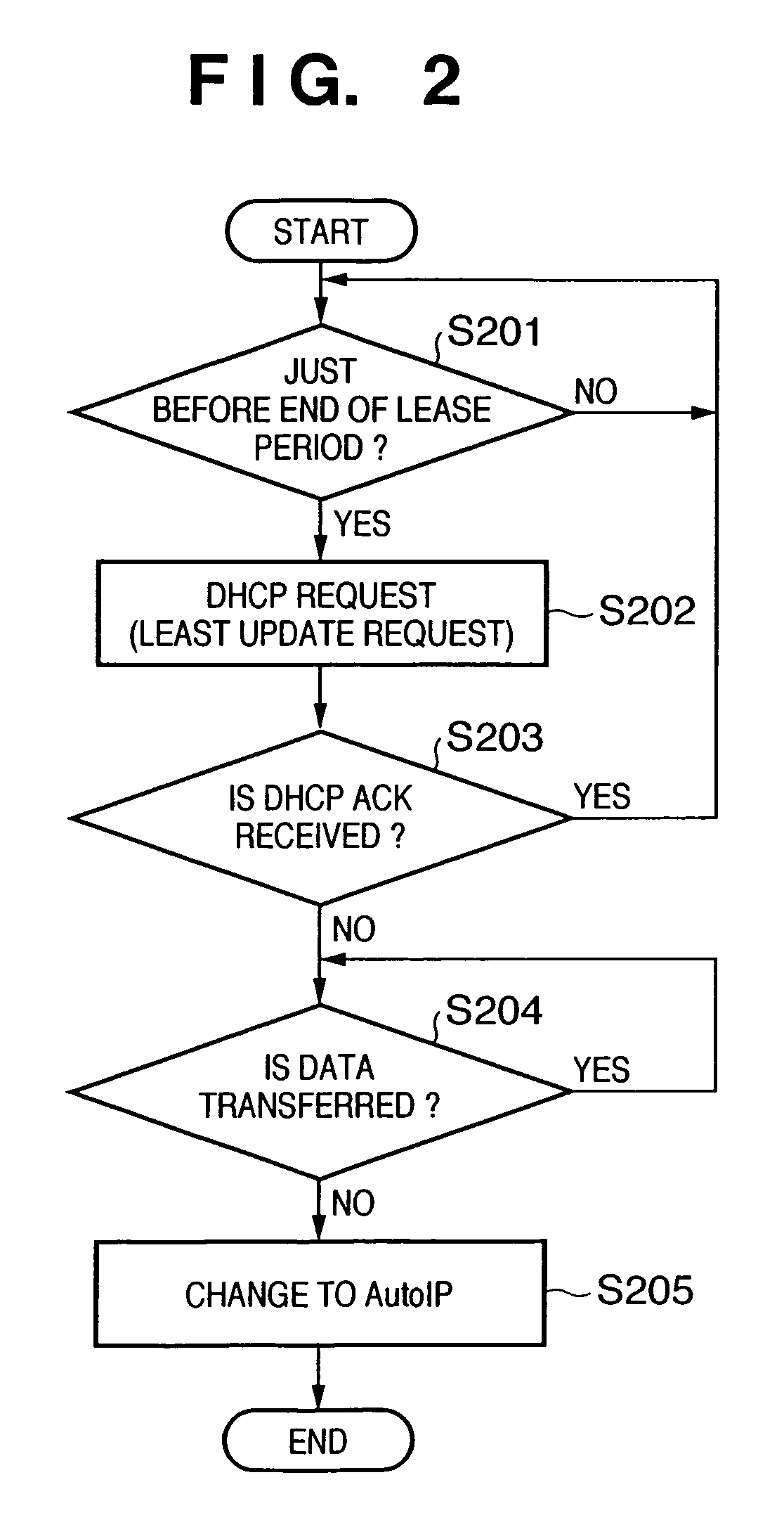
A communication apparatus such as a digital video camcoder acquires an IP address from a DHCP server on a UPnP network. During the communication apparatus is transmitting an image stream, which is a sensed image, to the DTV, the communication apparatus issues an IP address update request to the DHCP server. In this case, when the DHCP server leaves the UPnP network, the communication apparatus keeps transmitting the stream while holding an already set IP address. Upon completely transmitting the series of the stream, the communication apparatus generates its own IP address using an AutoIP function.

Description

FIELD OF THE INVENTION[0001]The present invention relates to a technique for acquiring and updating an IP address in a communication apparatus such as an image sensing apparatus which communicates with a network using the IP address.BACKGROUND OF THE INVENTION[0002]In recent years, a network technique for searching for a device which provides a predetermined service on a network has been developed. As one example of this technique, Microsoft Corporation proposes UPnP (Universal Plug and Play) (for example, a reference “Universal Plug and Play Device Architecture Version 1.0, 08 Jun. 2000 10:41 AM”). UPnP defines a “service”, “device”, and “control point”. The service is a logical unit for providing a predetermined service, the device is a logical unit including one or more services, and the control point is a logical unit for controlling the one or more services.[0003]UPnP includes Internet standard techniques such as IP, TCP, UDP, and HTTP. With reference to the above reference whi...

Claims


Application Information

Patent Timeline
Patent Type & Authority Patents(United States)
IPC IPC(8): G06F15/16G06F15/177H04L29/12H04L12/46H04N5/232
CPCH04L12/2807H04L61/2092H04L61/2015H04L29/1232H04L61/5092H04L61/5014
Inventor FUJITA, SHUNJI
Owner CANON KK
Learn More