Systems and methods of a gutter cleaning system

a technology of gutter cleaning and multi-functionality, applied in the field of gutter cleaning systems, can solve the problem of prohibitively dangerous tasks for users, and achieve the effects of facilitating computer programming of facilitating onboard power base or module functions

Inactive Publication Date: 2011-04-19
UMAGINATION LABS
View PDF107 Cites 36 Cited by
  • Summary
  • Abstract
  • Description
  • Claims
  • Application Information

AI Technical Summary

Problems solved by technology

Further, some tasks are prohibitively dangerous for a user wishing to complete the task by themselves, such as gutter cleaning from the top of a ladder.

Method used


Image

  • Systems and methods of a gutter cleaning system
  • Systems and methods of a gutter cleaning system
  • Systems and methods of a gutter cleaning system

Examples


Embodiment Construction

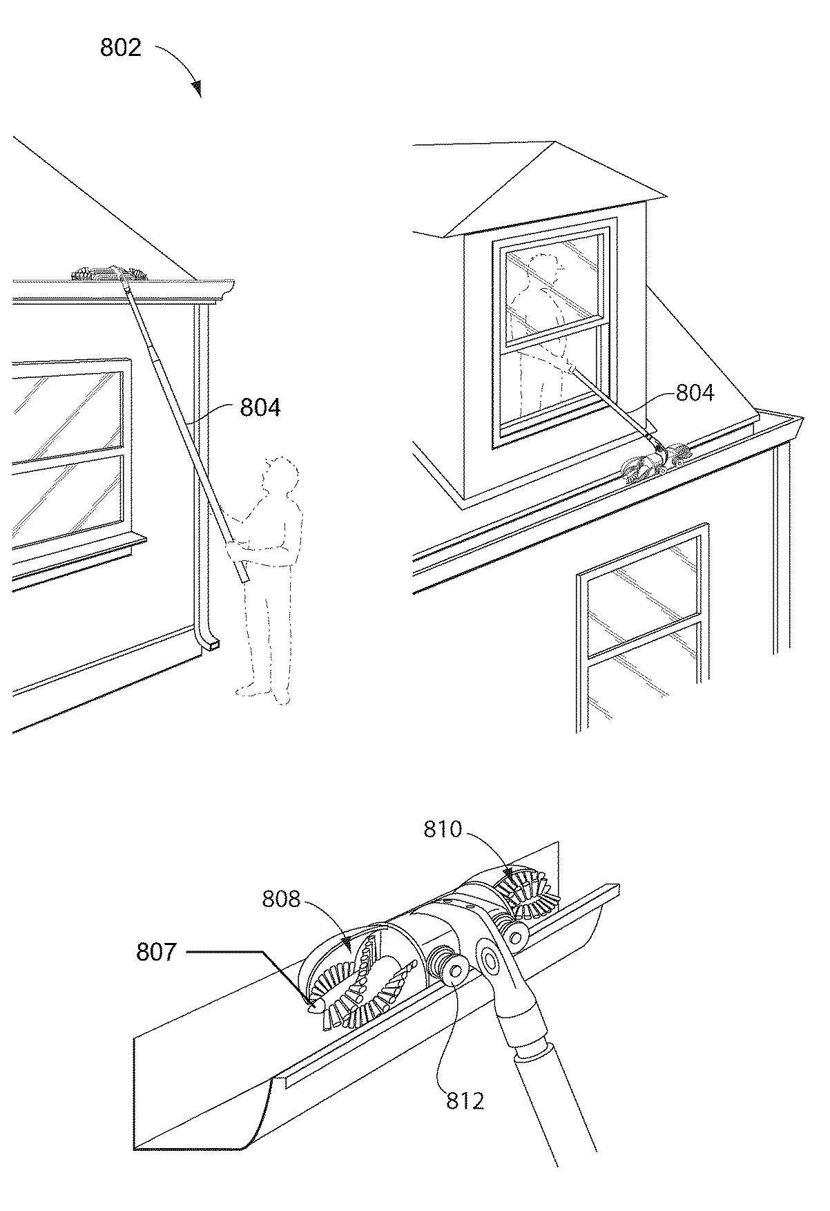
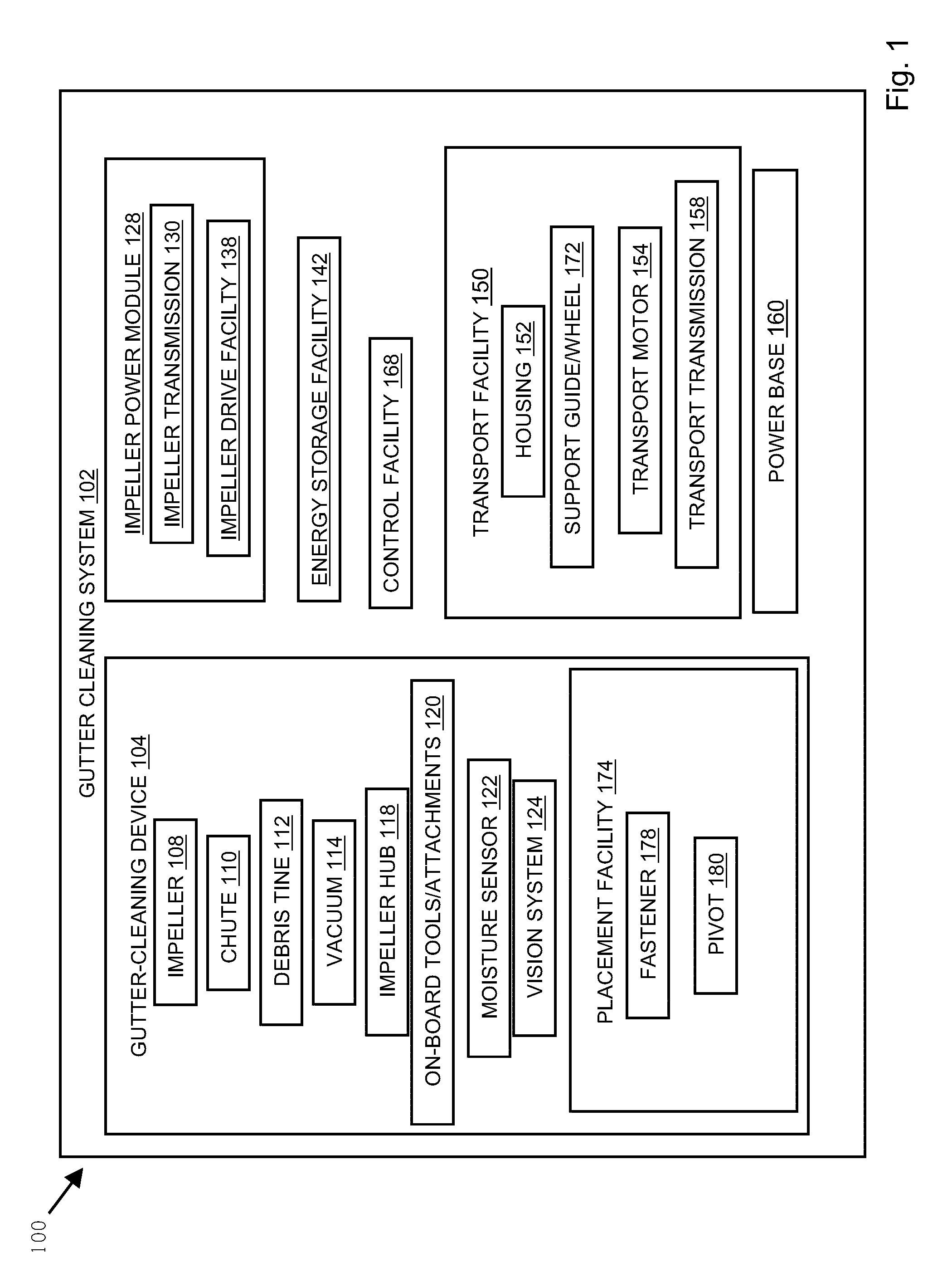
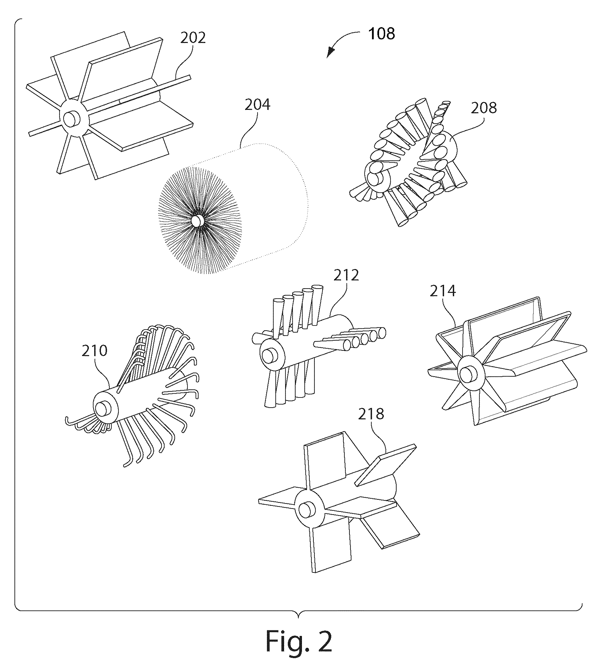
[0036]A gutter cleaning system may comprise a gutter-cleaning device and a placement facility, wherein the functional elements of the gutter-cleaning device may be disposed within the gutter-cleaning device, or wherein at least a portion of the functional elements of the gutter-cleaning device are disposed within the power base. The power base may provide the ability to use a single base piece that provides power, handling, and the like, to which modules with different functions may be attached. Thus, the power base may eliminate the need to purchase, store, and maintain multiple power tools for each function that may be accomplished by a particular module. A user may deploy the gutter cleaning system by lifting or lowering a gutter-cleaning device attached to an end of a placement facility or power base into a gutter. A user may maneuver the gutter-cleaning device along the gutter while it disposes of gutter debris using rotating impellers on at least one end of the gutter-cleaning...


PUM


Abstract

In embodiments of the present invention, a method of a gutter cleaning system comprises providing a housing configured to fit into a gutter, disposing at least one impeller at an end of the housing, driving the impeller with an impeller drive facility, the impeller drive facility being disposed within the housing, and attaching the housing to a placement facility for guiding the housing along the gutter.

Description

CROSS-REFERENCE TO RELATED APPLICATIONS[0001]This application claims the benefit of the following provisional applications, each of which is hereby incorporated by reference in its entirety: U.S. provisional patent application Ser. No. 60 / 837,993, filed Aug. 15, 2006; and U.S. Provisional patent application Ser. No. 60 / 952,938, filed Jul. 31, 2007.BACKGROUND[0002]1. Field[0003]The present invention generally relates to systems and methods for a multi-functional power tool system, and in particular, a gutter cleaning system.[0004]2. Description of the Related Art[0005]Tools are often designed to carry out a single function, and thus, an individual may need to purchase and maintain multiple tools, such as a tool for each task they may want to complete, where a tool may facilitate completion of the task. Further, some tasks are prohibitively dangerous for a user wishing to complete the task by themselves, such as gutter cleaning from the top of a ladder. A need exists for a tool that i...

Claims


Application Information

Patent Timeline
Patent Type & Authority Patents(United States)
IPC IPC(8): E04D13/076
CPCE04D13/0765A46B13/001A46B2200/3073A46B13/02
Inventor DAYTON, DOUGLAS C.PARK, SUNGFLORENCE, MARK R
Owner UMAGINATION LABS
Why Eureka
Try Eureka