Optical cellulose acylate film, polarizing plate and liquid crystal display

a technology of optical cellulose and acylate film, applied in the direction of instruments, transportation and packaging, synthetic resin layered products, etc., can solve the problems of difficult to increase birefringence, severe demands for viewing angle dependency, and insufficient satisfaction, and achieve small changes in viewing angle characteristics, small fluctuations in retardation value, and excellent increasability of retardation in film plane and in thickness direction.

Active Publication Date: 2011-04-19
FUJIFILM CORP
View PDF18 Cites 7 Cited by
  • Summary
  • Abstract
  • Description
  • Claims
  • Application Information

AI Technical Summary

Benefits of technology

[0028]An embodiment of a cellulose acylate film of the invention and an embodiment of a polarizing plate using the same are excellent in increasability of a retardation in a film plane and a retardation in a direction perpendicular to the film plane (i.e., a thickness direction), and additives do not bleed out therefrom.

Problems solved by technology

However, in a liquid crystal display for TV use which is assumed to be viewed from various angles in a large-sized screen, demands towards viewing angle dependency are severe, and the demands have not been satisfied even by the technique as described above.
In general, it is known that cellulose triacetate is a polymer material difficult to be stretched, so that it is difficult to increase birefringence.
However, it has become difficult to realize a desired retardation value because of bleeding out of additives or breakage of the film in stretching.
Further, the liquid crystal displays are increasingly frequently used under various environments, and the cellulose ester film used in the above-mentioned technique has the problem that the optical compensating function thereof varies under the environments.
In particular, there has been the problem that when the cellulose ester film is bonded to the liquid crystal cell, it is influenced by changes in the environment, particularly changes in humidity, to cause changes in Re retardation value and Rth retardation value thereof, resulting in changes in optical compensating ability.

Method used


Image

  • Optical cellulose acylate film, polarizing plate and liquid crystal display
  • Optical cellulose acylate film, polarizing plate and liquid crystal display
  • Optical cellulose acylate film, polarizing plate and liquid crystal display

Examples


example 1

1. Formation of Cellulose Acylate Films

(1) Cellulose Acylates

[0219]Cellulose acylates described in Table 1, which are different in the degree of acetyl substitution, were prepared. Acylation reaction was conducted at 40° C. by adding sulfuric acid (7.8 parts by weight based on 100 parts by weight of cellulose) as a catalyst, and adding a carboxylic acid. Then, the amount of the sulfuric acid catalyst, the amount of water and the ageing time were adjusted to adjust the total degree of substitution and the degree of substitution at the 6-position. The ageing temperature was 40° C. Further, low molecular weight components of this cellulose acylate were removed by washing with acetone.

(2) Preparation of Chlorine-Based Organic Solvent Dopes

[0220]Each of the cellulose acylates described in Table 1 and a plasticizer (a 2:1 mixture of triphenyl phosphate and biphenyldihenyl phosphate) were put into a mixed solvent of dichloromethane / methanol (87 / 13 parts by weight) with stirring to yield a ...

example 2

(Preparation of Polarizing Plates-1)

[0225]Iodine was allowed to be adsorbed by a stretched polyvinyl alcohol film to prepare a polarizer.

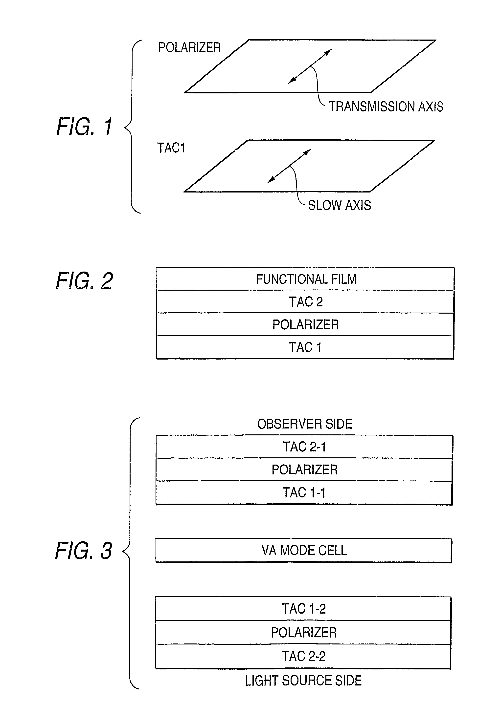
[0226]Each of the cellulose acylate films prepared in Example 1 (F1 to F8: corresponding to TAC 1 of FIGS. 1 and 2 or TAC 1-1 or 1-2 of FIG. 3) was subjected to saponification treatment, and was bonded to one side of the polarizer with a polyvinyl alcohol-based adhesive. Saponification treatment was performed under the following conditions.

[0227]A 1.5 N sodium hydroxide aqueous solution was prepared and kept warm at 55° C. A 0.01 N diluted sulfuric acid aqueous solution was prepared and kept warm at 35° C. The cellulose acylate film prepared was immersed in the above-mentioned sodium hydroxide aqueous solution for 2 minutes, and then, immersed in water to thoroughly wash away the sodium hydroxide aqueous solution. Then, the film was immersed in the above-mentioned diluted sulfuric acid aqueous solution for 1 minute, and then, immersed in water to t...

example 3

(Mounting to VA Panel)(One Sheet Type)

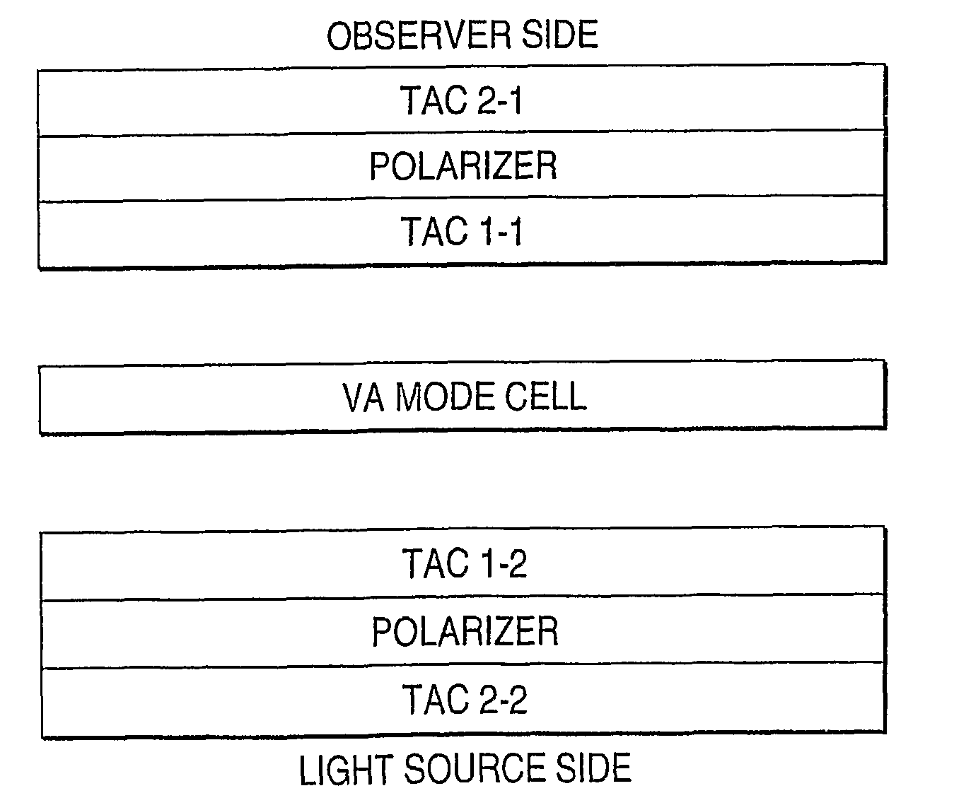
[0262]A liquid crystal display of FIG. 3 was prepared. That is to say, an upper polarizing plate (TAC 2-1 (having a functional film / no functional film), a polarizer and TAC 1-1), a VA mode liquid crystal cell and a lower polarizing plate (TAC 1-2, a polarizer and TAC 2-2) were laminated from the observer side (upper side), and a back light source was arranged. In the following example, a commercially available polarizing plate (HLC2-5618) was used as the upper polarizing plate, and a polarizing plate formed integrally with an optical compensating film was used as the lower polarizing plate. However, even when this arrangement is reversed, there is no problem functionally. The integral type polarizing plate is preferably used as the lower polarizing plate (because when it is used as the upper polarizing plate, it is necessary to provide the functional film on the observer side (upper side), which may cause a decrease in production yield ratio), a...


PUM

PropertyMeasurementUnit
thicknessaaaaaaaaaa
RHaaaaaaaaaa
RHaaaaaaaaaa

Abstract

A cellulose acylate film is provided and is excellent in increasability of an in-plane retardation and a retardation in a thickness direction, from which an additive does not bleed out, and which is excellent in surface properties. The cellulose acylate film has a thickness of 40 μm to 180 μm and contains no retardation increasing agent. Retardation values Re and Rth of the cellulose acylate film meet the following formulae (III) to (V):46≦Re≦100  (III)Rth=a−5.9Re  (IV)520≦a≦670  (V)A polarizing plate and a VA mode liquid crystal display having wide viewing angle characteristics and small changes in color, which are using the cellulose acylate film, are provided.

Description

[0001]This application is a 371 of PCT / JP05 / 12260 filed Jun. 27, 2005.TECHNICAL FIELD[0002]The present invention relates to a cellulose acylate film for optical use, and a polarizing plate and liquid crystal display using the cellulose acylate film.BACKGROUND ART[0003]Liquid crystal displays have been widely utilized for personal computer use, monitor use of portable devices and television use because of various advantages such as low voltage, low power consumption and possibility of miniaturization and thickness decreasing. In such liquid crystal displays, there have been proposed various modes according to the state of arrangement of liquid crystals in liquid crystal cells. However, a TN mode has hitherto prevailed in which a liquid crystal is twist-orientated through about 90 degrees from a lower substrate of a crystal cell toward an upper substrate thereof.[0004]In general, the liquid crystal display comprises liquid crystal cells, optical compensating sheets and polarizers. The...

Claims


Application Information

Patent Timeline
Patent Type & Authority Patents(United States)
IPC IPC(8): G02F1/13363G02F1/335
CPCC08J5/18G02B5/3033G02B5/3083C08J2301/14Y10T428/1036G02F1/13363G02F1/1393Y10T428/1041Y10T428/105G02F1/133528C09K2323/03C09K2323/031C09K2323/035C08J5/22C08L1/10G02F1/1335
Inventor OHTANI, SUMIOKAWANISHI, HIROYUKISATAKE, SEIMI
Owner FUJIFILM CORP
Why Eureka
Try Eureka