Sensor assembly with conductive bridge

a technology of electroencephalogram and sensor assembly, which is applied in the field of electroencephalogram sensor for can solve the problems of messy application of gel and paste, affecting the recording data, and affecting the accuracy of electrophysiological signals, so as to promote accurate low impedance. , the effect of promoting the measurement of electrophysiological signals

Inactive Publication Date: 2011-04-19
COMPUMEDICS
View PDF12 Cites 7 Cited by
  • Summary
  • Abstract
  • Description
  • Claims
  • Application Information

AI Technical Summary

Benefits of technology

[0005]The conductive bridge may be placed between an electrode and a patient's skin. In one embodiment, the conductive bridge is an assembly comprised of an expandable member with an absorbent material attached to one end. An aperture extends through the expandable member, forming a cavity well. The addition of a conductive medium to the cavity well allows the conductive bridge to provide a conductive pathway for electrophysiological signals emanating from the patient. When a conductive medium is added to the cavity well, the medium is absorbed into the expandable member. The absorption of conductive medium causes the expandable member to expand vertically. When used with an EEG cap, this expansion develops moderate pressure to maintain the conductive bridge against the patient's skin.
[0006]The conductive bridge can be used as a substitute for or in addition to the conductive gel or paste that is often used when measuring electrophysiological signals. For example, it can be used in disk electrode-based EEG caps. Embodiments of the invention provide a low impedance sensor, thereby promoting accurate measurement of electrophysiological signals. Minimal impedance is desired as a reduced impedance allows the electrode to obtain a stronger and more accurate reading of electrophysiological signals.
[0007]Embodiments of the invention also promote easy clean-up for the test subject, when compared to gel or paste methods. Further, embodiments of the present invention are able to slowly dispense conductive media from a cavity well to the expandable member over time, thereby enabling consistent measurement of electrophysiological signals over a prolonged time period.

Problems solved by technology

While this method generally works for its intended purpose, there are some disadvantages to the uses of gels and pastes.
Secondly, the gel or paste may dry after prolonged use, thus also affecting the recorded data.
Thirdly, gels and pastes can be messy when applied, especially in cases such as EEG tests wherein the electrode is placed over thick hair.

Method used


Image

  • Sensor assembly with conductive bridge
  • Sensor assembly with conductive bridge
  • Sensor assembly with conductive bridge

Examples


Embodiment Construction

[0016]For the purpose of explanation only, the subject invention is described with respect to an embodiment which is adapted for use in recording EEG signals. One skilled in the art can readily ascertain that the subject invention may be applicable for other uses wherein electrophysiological signals are taken.

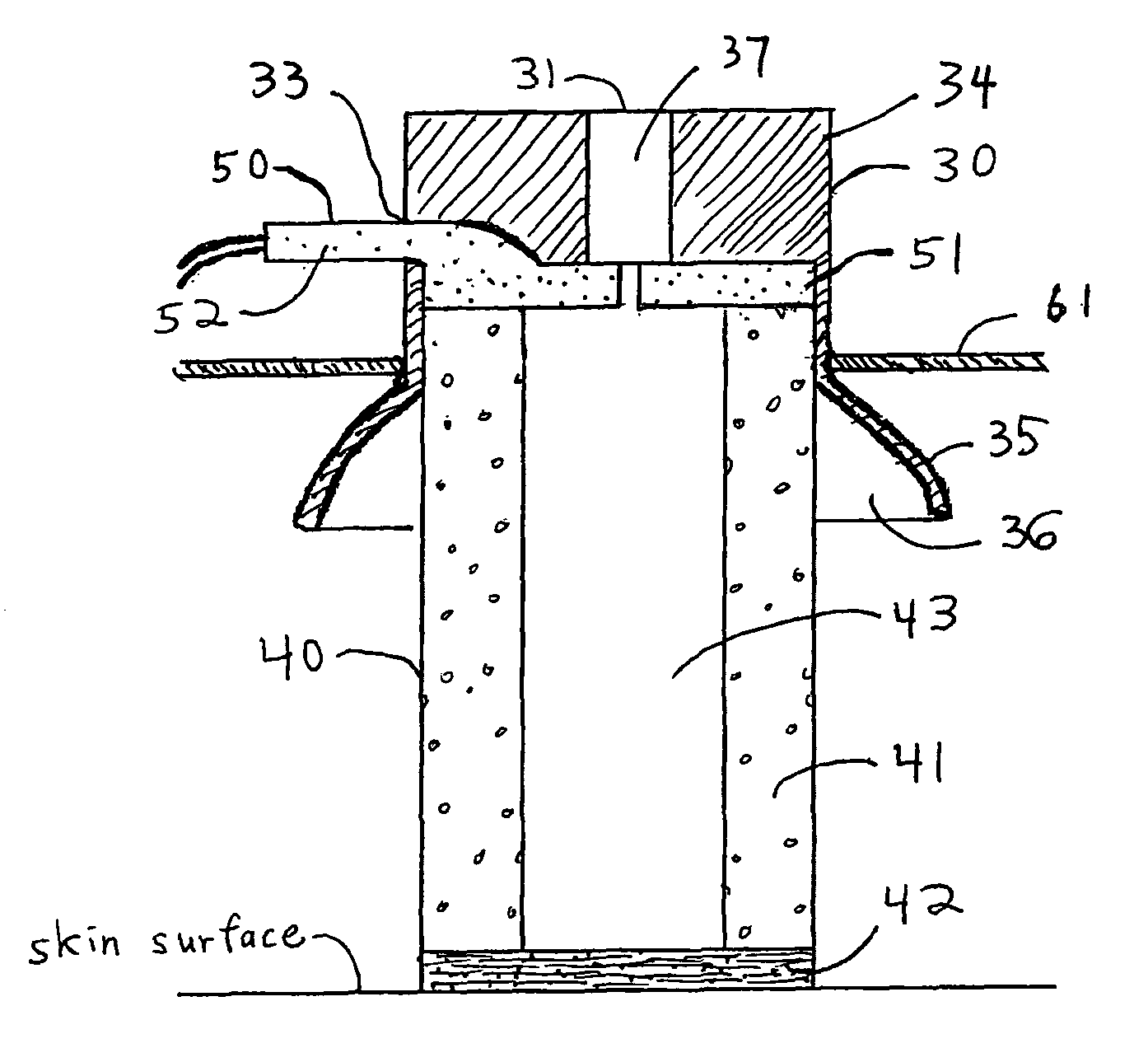
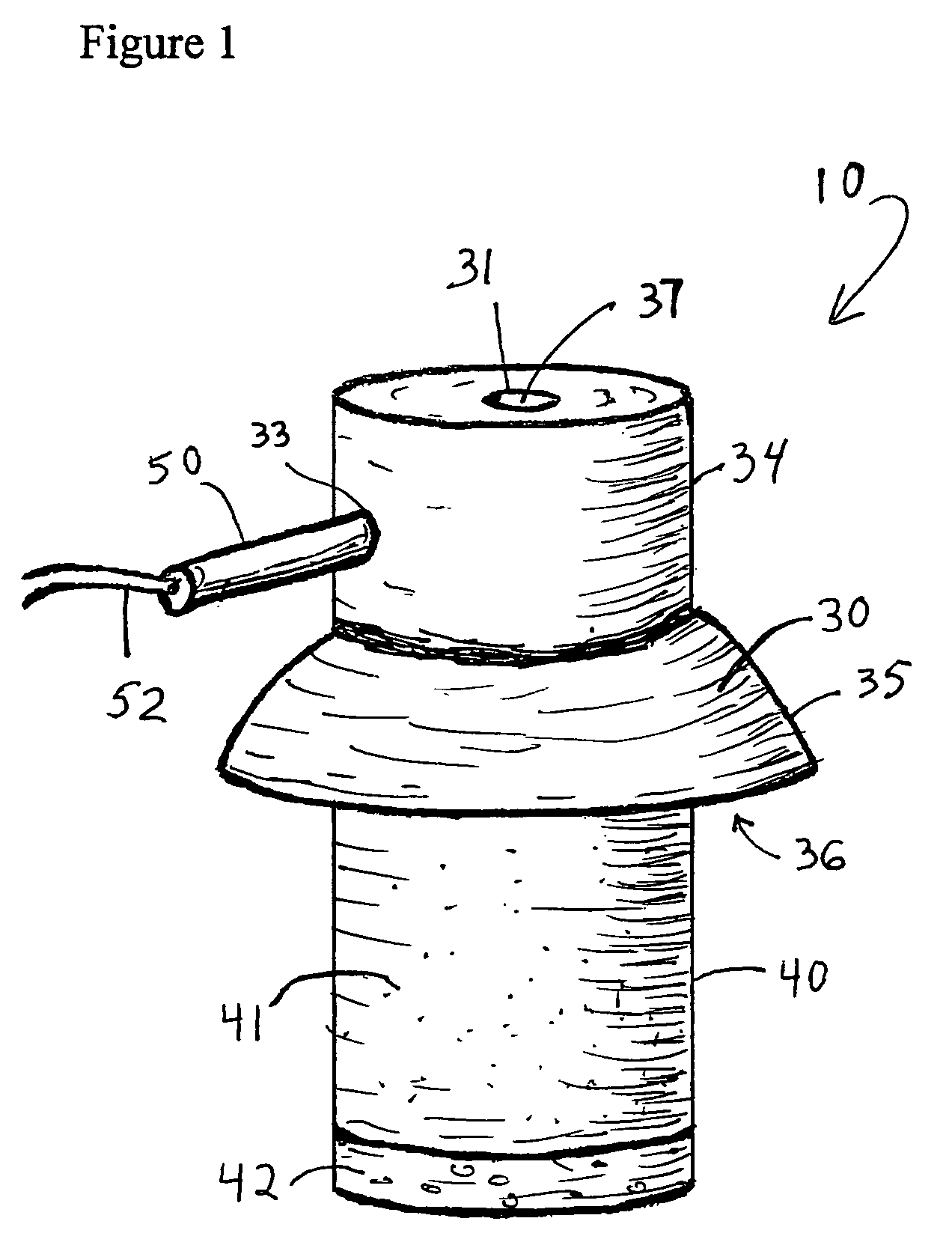
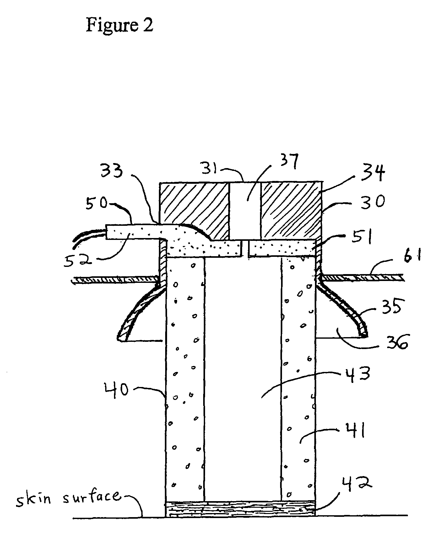
[0017]The subject invention relates to an electrode assembly 10 comprised of a housing 30, an electrode 50, and a conductive bridge 40.

[0018]As shown in FIG. 2, the subject invention also relates to a conductive bridge 40 placed between electrode 50 and a patient's skin in order to provide a conductive pathway for electrophysiological signals emanating from the patient. As shown in FIG. 1, in one embodiment, the subject conductive bridge 40 is a generally cylindrical (although other shapes may be used) assembly comprised of an expandable member 41 with an absorbent material 42 attached to one end. As shown in FIGS. 2 and 4, an aperture extends through expandable member 41 and t...


PUM


Abstract

A sensor assembly for the measurement of electrophysiological signals and including a conductive bridge is provided. In one embodiment, the conductive bridge is provided by an expandable member with an absorbent material attached to one end. An aperture extends through the expandable member, forming a cavity well. Addition of a conductive medium to the cavity well allows the conductive bridge to provide a conductive pathway between an electrode and a patient's skin.

Description

RELATED APPLICATION[0001]This application claims the benefit of U.S. Provisional Application No. 60 / 695,554, filed Jun. 29, 2005.FIELD OF THE INVENTION[0002]The invention relates generally to sensors for the measurement of electrophysiological signals, and more particularly an electrode assembly for monitoring electroencephalogram (EEG) signals.BACKGROUND[0003]When measuring a patient's electrophysiological signals, a conductive bridge is typically used between an electrode and the patient's skin in order to provide electrical communication between the skin and the electrode. Previously, most conductive bridges were simply gels or pastes placed between the electrode and skin. While this method generally works for its intended purpose, there are some disadvantages to the uses of gels and pastes. For example, air pockets may form in gels or pastes and these air pockets could affect the accuracy of the readings. Secondly, the gel or paste may dry after prolonged use, thus also affectin...

Claims


Application Information

Patent Timeline
Patent Type & Authority Patents(United States)
IPC IPC(8): A61B5/0478A61B5/296
CPCA61B5/0478A61B5/6814A61B2562/125A61B5/291
Inventor PONTON, CURTIS W.
Owner COMPUMEDICS
Why Eureka
Try Eureka