Logical to physical connectivity verification in a predefined networking environment

a networking environment and verification technology, applied in error detection/correction, instruments, digital computers, etc., can solve problems such as inability to easily and accurately, difficult to correlate physical to logical connectivity, and limitations that plague generations of system owners

Inactive Publication Date: 2011-04-19
IBM CORP
View PDF12 Cites 4 Cited by
  • Summary
  • Abstract
  • Description
  • Claims
  • Application Information

AI Technical Summary

Benefits of technology

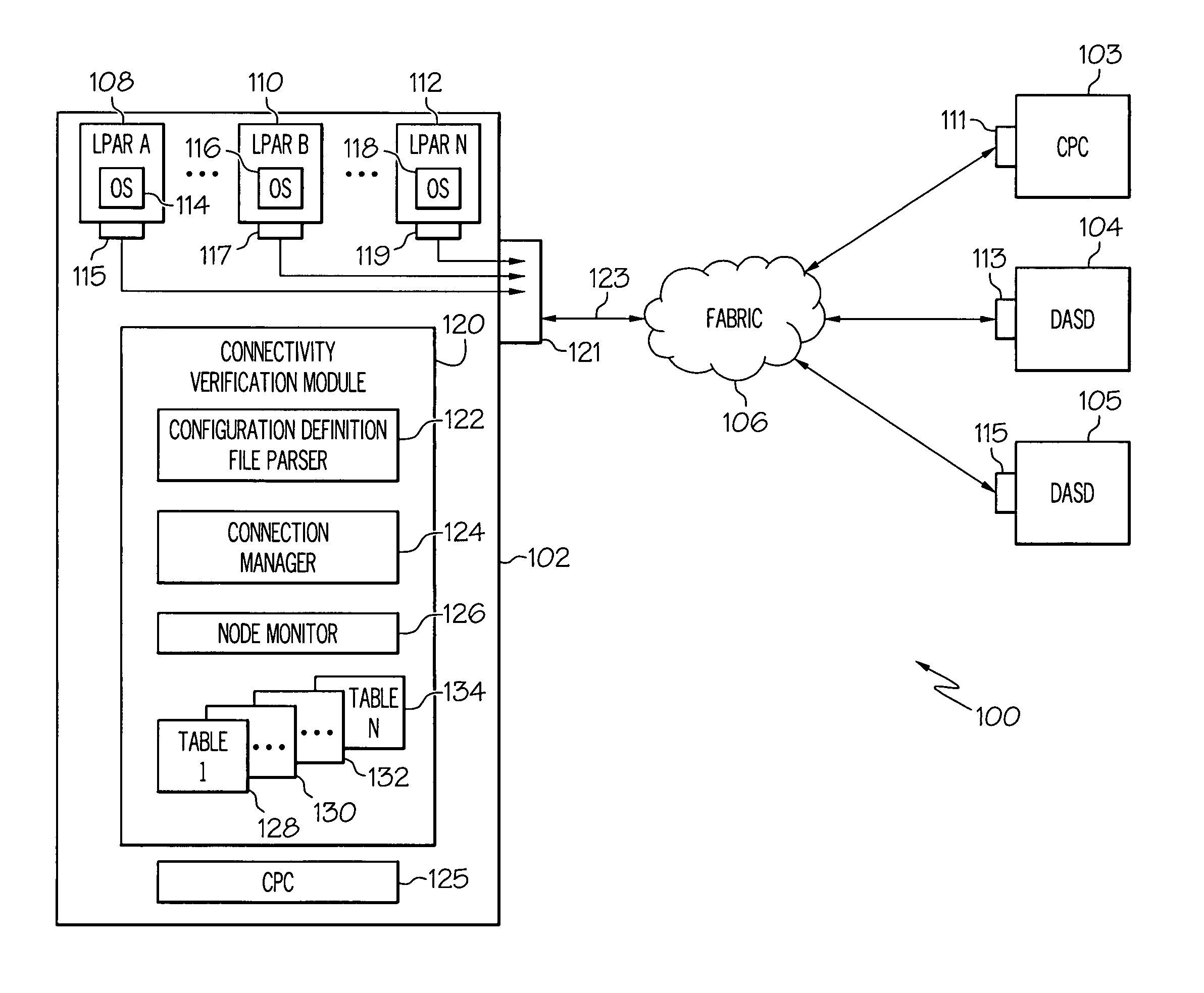
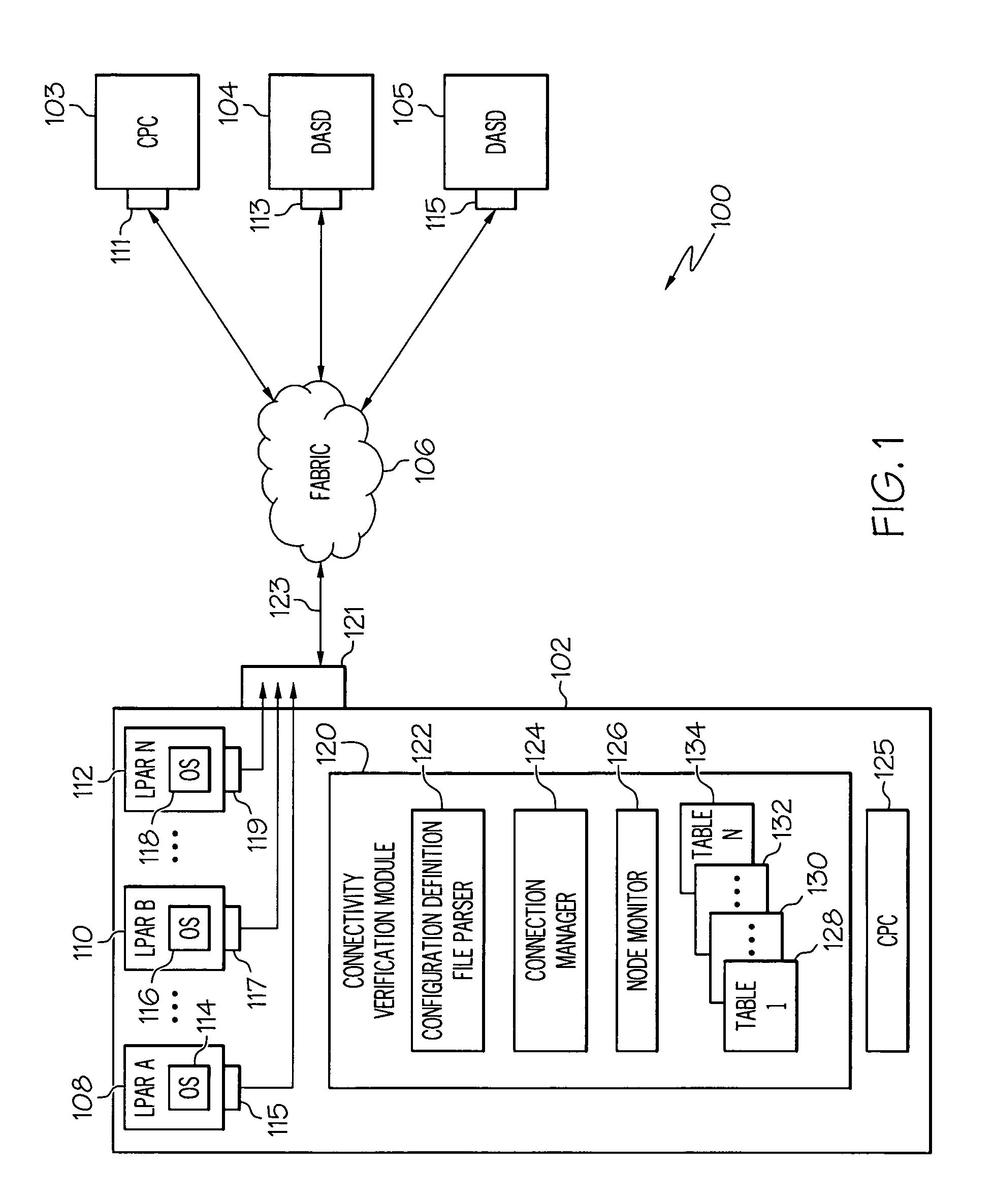
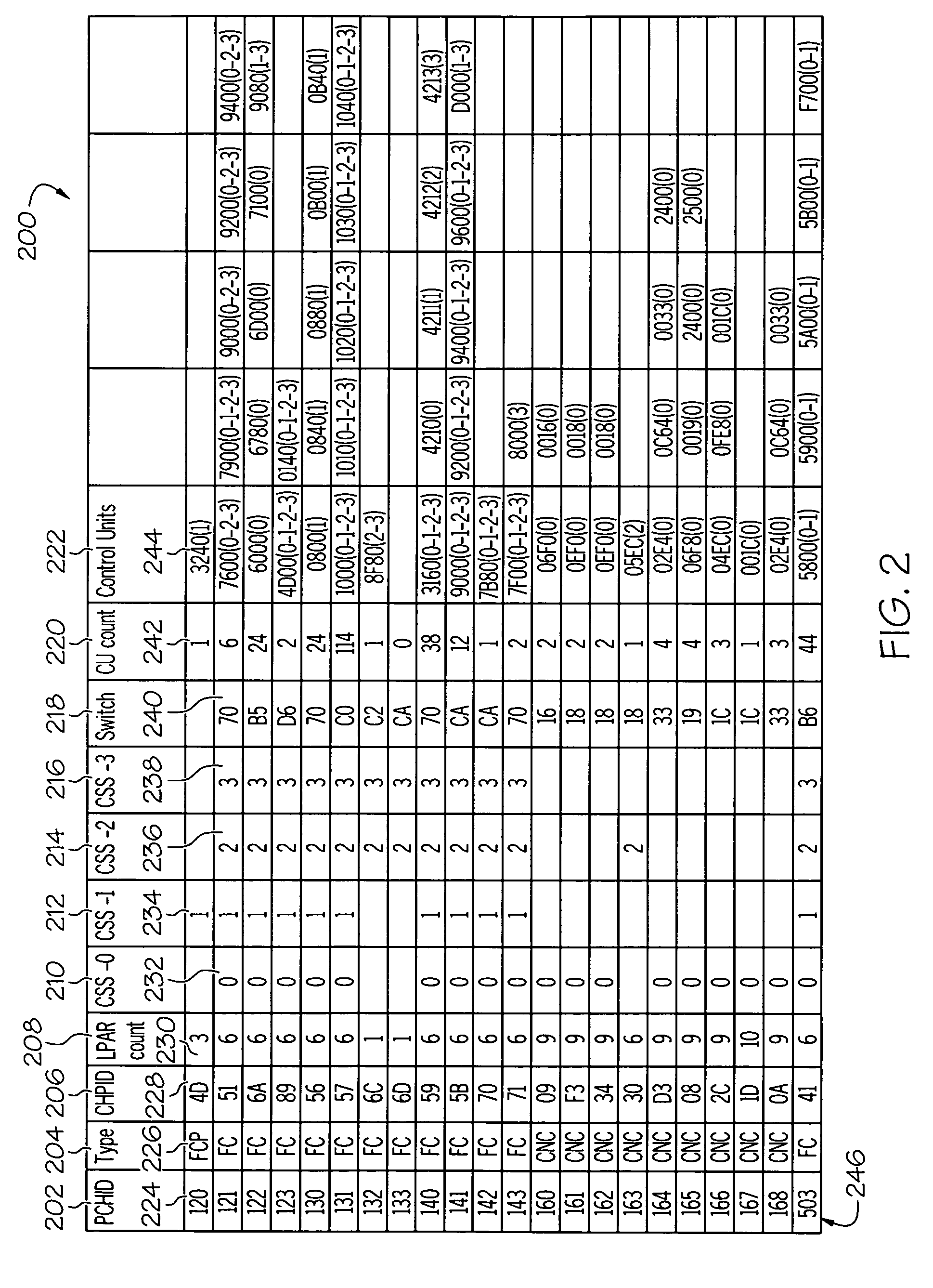
[0007]One advantage of the various embodiments of the present invention is that logical to physical connectivity within a networking environment can be verified. Connectivity information can be presented to a user from various perspectives such as from a channel, a control unit, a node, a link, and other perspectives. Connectivity information can be formatted into sortable tables so that a user can identify any misconfigurations, over utilization of resources, single points of failure, or other problems with the predefined logical-to-physical connections. Another advantage is that broken paths can be identified from the physical perspective as compared to the logical perspective of the individual operating systems.

Problems solved by technology

One current limitation found in many network computing environments is the ability to easily and accurately verify the physical and logical connectivity as described by their static definition.
Such a limitation has plagued generations of system owners.
However, this still leaves the task of ensuring the logical definitions to the customer.
Current tools outside the processor generally do not have access to the static definition file, which makes it difficult to correlate the physical to logical connectivity.

Method used


Image

  • Logical to physical connectivity verification in a predefined networking environment
  • Logical to physical connectivity verification in a predefined networking environment
  • Logical to physical connectivity verification in a predefined networking environment

Examples


Embodiment Construction

[0013]As required, detailed embodiments of the present invention are disclosed herein; however, it is to be understood that the disclosed embodiments are merely examples of the invention, which can be embodied in various forms. Therefore, specific structural and functional details disclosed herein are not to be interpreted as limiting, but merely as a basis for the claims and as a representative basis for teaching one skilled in the art to variously employ the present invention in virtually any appropriately detailed structure and function. Further, the terms and phrases used herein are not intended to be limiting; but rather, to provide an understandable description of the invention.

[0014]The terms “a” or “an”, as used herein, are defined as one or more than one. The term plurality, as used herein, is defined as two or more than two. The term another, as used herein, is defined as at least a second or more. The terms including and / or having, as used herein, are defined as comprisin...


PUM


Abstract

A method, information system, and computer readable storage medium verify predefined connectivity for I / O devices. Current predefined logical connection data and actual physical connection data is gathered. The predefined logical connection data and the actual physical connection data are formatted into a plurality of sortable tables. At least a portion of the predefined logical connection data is formatted into a predefined channels table and at least a portion of the actual physical connection data is formatted into a node information table. The portion of the predefined logical connection data is compared with the portion of the actual physical connection data. The portion of the predefined logical connection data is determined to substantially match / not match the portion of the actual physical connection data. At least one predefined logical connection associated with the predefined logical connection data that fails to substantially match the actual physical connection data is displayed to a user.

Description

FIELD OF THE INVENTION[0001]The present invention generally relates to the field of predefined networking environments, and more particularly relates to verifying logical to physical connectivity within a networking environment.BACKGROUND OF THE INVENTION[0002]One current limitation found in many network computing environments is the ability to easily and accurately verify the physical and logical connectivity as described by their static definition. Such a limitation has plagued generations of system owners. Typically, in order to acquire the necessary data to begin verification, data collection is generally performed by the various directors, usually from an array of different vendors. Current tools provide the system owner with information associated with the actual physical connections. However, this still leaves the task of ensuring the logical definitions to the customer. Current tools outside the processor generally do not have access to the static definition file, which make...

Claims


Application Information

Patent Timeline
Patent Type & Authority Patents(United States)
IPC IPC(8): G06F11/00
CPCH04L43/0811
Inventor BORELLI, MARIO L.SPOTTS, JUSTIN M.TENYENHUIS, TRISTAN A.
Owner IBM CORP
Why Eureka
Try Eureka