Scraper blade assembly structure

a technology of assembly structure and scraper blade, which is applied in the direction of building repair, construction, metal working apparatus, etc., can solve the problems of insufficient tightening force of scraper blade, risk of loose assembly and detachment, and hand fingers being hurt, etc., to facilitate effective scraping and strong hand grasping. , the effect of fast replacemen

Active Publication Date: 2011-04-26
LIN WEN CHEN
View PDF16 Cites 9 Cited by
  • Summary
  • Abstract
  • Description
  • Claims
  • Application Information

AI Technical Summary

Benefits of technology

[0009]The objective for the invention is to provide a scraper blade assembly structure. It mainly comprises a jaw plate that extends backward to form an arm and a scraping section that has a jaw plate groove to accommodate the jaw plate by a fastener, which also serves as a lever pivot. When fastening buttons are placed into the jaw plate groove in the scraping section, they are sleeved with spring to provide pushing force against the arm, and therefore the front end of the jaw plate can exert a great force to the blade. In this way, a fast replacement and firm assembly for scraper blade is achievable.
[0010]Another objective for the invention is to provide a scraper blade assembly structure that the fastening buttons in the jaw plate in the scraping section further become protruding spheres on the side of the scraping section to facilitate strong hand grasping for effective scraping.
[0011]To achieve the above objective, the scraper blade assembly structure in the invention mainly comprises a jaw plate that extends backward to form an arm to combine with the jaw plate groove of the scraping section by a fastener that also serves as a lever pivot. The arm can swing back and forth inside the jaw plate groove. The scraping section uses its terminal connecting section to connect with the stem. On one side of the scraping section, there is a jaw plate groove to accommodate the jaw plate. When the fastening button is placed inside the jaw plate groove of the scraping section, it is sleeved with a spring to provide pushing force against the arm, and therefore the front end of the jaw plate can tightly hold the plate in position with the blade base in the front of the jaw plate groove. By turning the fastening button to push against the arm, the front end of the jaw plate generates an extremely strong hold of the blade. On the other hand, by turning the fastening button to release the hold, fast replacement and firm assembly for the blade are achievable.

Problems solved by technology

In consequence, loosening three screws 17 during replacing the blade 16 causes some inconvenience.
In consequence, the tightening force to the blade 16 becomes insufficient.
There is a risk of loose assembly and detachment.
The hand grasping the front end of the stem 10 is very close to the surface, and therefore there is a risk of hurting the fingers of that hand.

Method used


Image

  • Scraper blade assembly structure
  • Scraper blade assembly structure
  • Scraper blade assembly structure

Examples


Embodiment Construction

[0020]A preferred embodiment is provided in the following to describe the features of the invention.

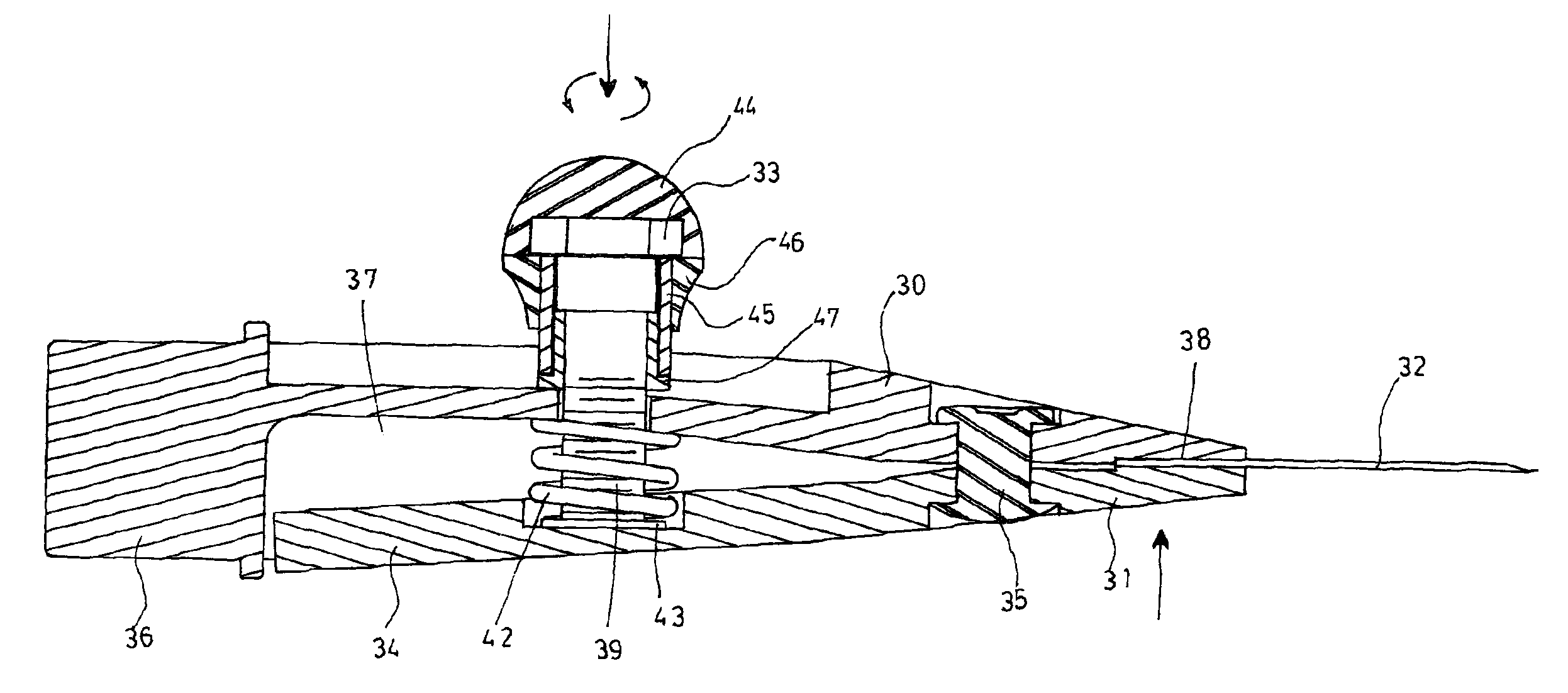
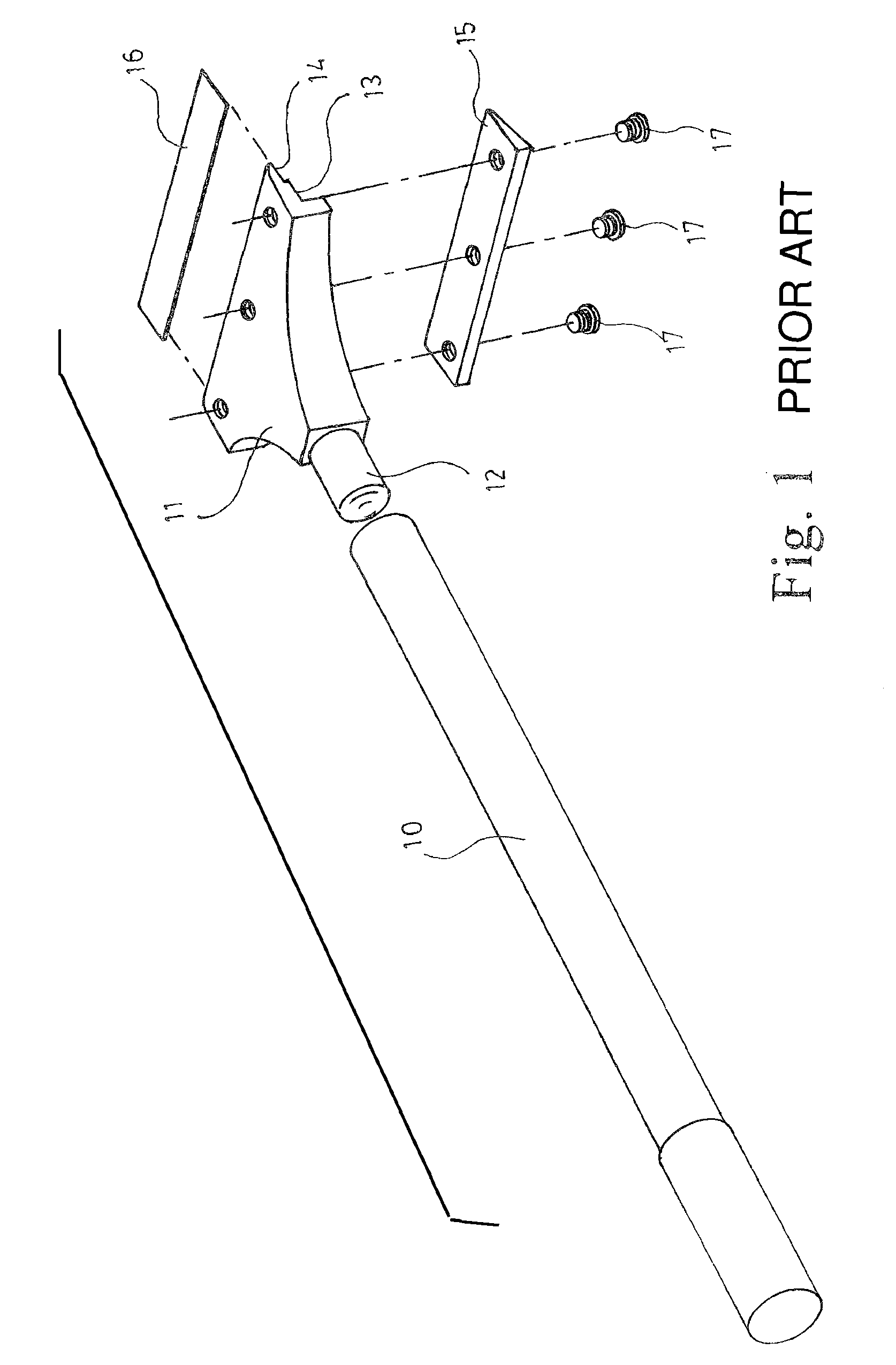
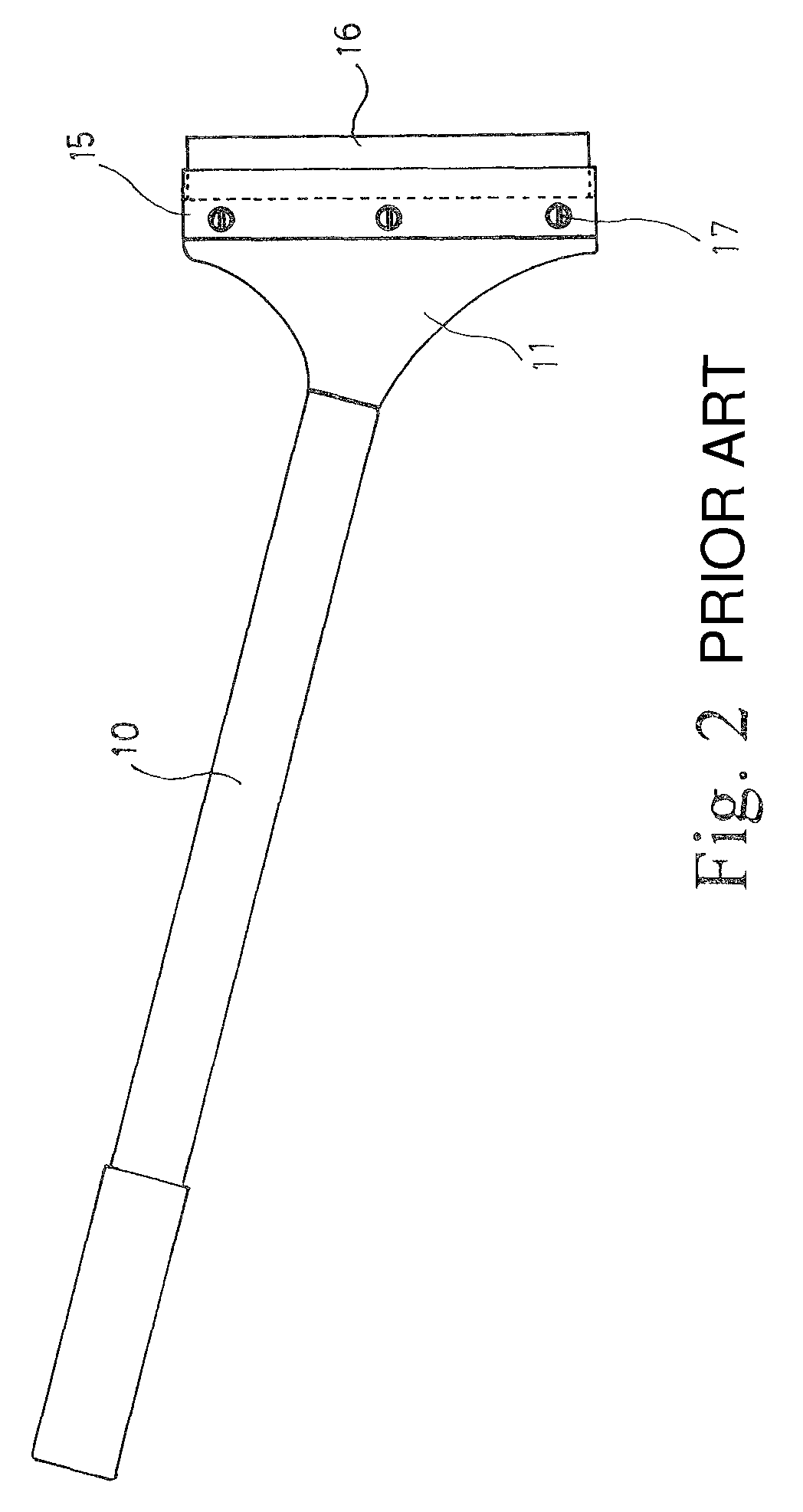
[0021]Please refer to FIGS. 3, 4, 5 and 6 for the disassembly diagram, assembly diagram and exterior diagram for the scraper blade assembly structure in the invention. In general the scraper is similar to the known types. It comprises a stem 20 for hand grip and a scraping section in the front. The front end and the back end for the stem 20 are sleeved with a handle 21, 22 for each, so the user can grasp between the front and the back handles 21, 22. The scraping section comprises a lower jaw plate 30, an upper jaw plate 31, a blade 32 and a fastening button 33. The upper jaw plate 31 extends backward to form an arm 34, and is attached by two fasteners 35 to the jaw plate groove 37 of the lower jaw plate 30, and is able to swing back and forth inside the jaw plate groove 37 by using the two fasteners 35 as lever pivot. The lower jaw plate 30 has its terminal connecting section 36 inse...


PUM


Abstract

The invention relates to a scraper blade assembly structure. The scraper includes a stem for hand grip and a scraping section in the front. The scraping section includes a jaw plate, a blade and a fastening button. The jaw plate extends backward to form an arm. The jaw plate is attached to the inside of the jaw plate groove of the scraping section by a fastener that also serves as a lever pivot for swinging back and forth. When a fastening button goes into the inside of the jaw plate of the scraping section, it pushes the inner side of the arm of the jaw plate, and so as to generate a great holding power for the front of the jaw plate. Further, the fastening button can be a handle protruding from one side of the scraping section.

Description

BACKGROUND OF THE INVENTION[0001]1. Field of the Invention[0002]The invention relates to a tool to remove surface residues in a remodeling project, especially for a scraper blade assembly structure. It is mainly to provide fast replacement for blade, firm assembly and a front stem for strong grip for effective stripping.[0003]2. Description of the Prior Art[0004]To assure the flatness in replacing wallpaper or carpet, it is necessary to remove the surface adhesive residue first. FIG. 1 and FIG. 2 show the structural disassembly diagram and assembly diagram for a known scraper. The scraper comprises a stem 10 for grip and a scraping section 11 at the front end. The back end of the scraping section 11 forms a connecting section 12 that can connect with the stem 10. At the front end there is a jaw 13 and a blade base 14 to accommodate a jaw plate 15 and a blade 16 in assembly. Through screws 17 tightening the jaw plate 15 and the scraping section 11, the jaw plate 15 in the jaw 13 sque...

Claims


Application Information

Patent Timeline
Patent Type & Authority Patents(United States)
IPC IPC(8): B26B3/00
CPCE04G23/006B44D3/164
Inventor LIN, WEN-CHEN
Owner LIN WEN CHEN
Why Eureka
Try Eureka