Fabric for protective garments

a fabric and protective garment technology, applied in the field of heat, flame and electric arc resistant fabrics, can solve the problems of affecting the respiratory activities of the wearer, the overall comfort of the wearer is usually very low, and the garment protecting against heat, flame and electric arc is usually very heavy, so as to improve the comfort of the wearer and achieve higher heat and vapor dissipation

Active Publication Date: 2011-04-26
DUPONT SAFETY & CONSTR INC
View PDF23 Cites 16 Cited by
  • Summary
  • Abstract
  • Description
  • Claims
  • Application Information

AI Technical Summary

Benefits of technology

[0013]Due to its peculiar structure, the fabric according to the present invention can have a specific weight which is considerably lower than that of known fabrics having comparable mechanical and thermal properties.
[0015]The garment according to the present invention strongly improves the wearer's comfort both during normal and critical situations. It is lighter and thinner than conventional garments having similar mechanical and thermal properties and it enables a higher heat and vapor dissipation from the wearer surface to the environment.

Problems solved by technology

A garment protecting against heat, flame and electric arc is usually very heavy because the mass and the thickness of the garment itself are normally the main factors conferring protection.
The wearer of such a garment, like for example the firefighter, is therefore limited in his movements and undergoes heat stress so that the overall wear comfort strongly decreases.
These materials confer more lightness to the final protective garment but they might affect the respiratory activities of the wearer due to their cumbersome dimensions.
Furthermore, the freedom of movement is not necessarily improved by using these materials.
However, this is usually associated with a decrease of the mechanical and thermal properties of the protective garment.
Such aramid fibers are used for the manufacture of garments which, due to the elevated specific weight of the fibers themselves, are heavy and rigid and, therefore, do not provide an adequate wear comfort.

Method used


Image

  • Fabric for protective garments
  • Fabric for protective garments
  • Fabric for protective garments

Examples


example 1

[0055]A blend of fibers, commercially available from E.I. du Pont de Nemours and Company, Wilmington, Del., U.S.A., under the trade name Nomex® N307, having a cut length of 5 cm and consisting of:

[0056]93 wt % of pigmented poly-metaphenylene isophthalamide (meta-aramid), 1.4 dtex staple fibers;

[0057]5 wt % of poly-paraphenylene terephthalamide (para-aramid) fibers; and

[0058]2 wt % of carbon core polyamide sheath antistatic fibers was ring spun into two types of single staple yarns (Y1 and Y2) using a conventional cotton staple processing equipment.

[0059]Y1 had a linear density of Nm 60 / 1 or 167 dtex and a twist of 850 Turns Per Meter (TPM) in Z direction and it was subsequently treated with steam to stabilize its tendency to wrinkle. Y1 was used as weft yarn.

[0060]Y2 had a linear density of Nm 70 / 1 or 143 dtex and a twist of 920 TPM in Z direction. Y2 was subsequently treated with steam to stabilize his tendency to wrinkle. Two Y2 yarns were then plied and twisted together. The resu...

example 2

[0076]Two plies weave fabrics with squared pockets of different sizes were prepared according to Example 1.

[0077]For the first ply, Y1 was used as weft and TY2 as warp.

[0078]For the second ply, the weft and warp were prepared as follows:

[0079]A blend of fibers, commercially available from E. I du Pont de Nemours and Company, Wilmington, Del., U.S.A., under the trade name Nomex® N305 having a cut length of 5 cm and consisting of:

[0080]75% pigmented poly-metaphenylene isophthalamide (meta-aramid) 1.7 dtex staple fibers;

[0081]23% poly-paraphenylene terephthalamide (para-aramid) fibers; and

[0082]2% of carbon core poyamide sheath antistatic fibers was ring spun into two types of single staple yarns (Y3 and Y4) using a conventional cotton staple processing equipment.

[0083]Y3 had a linear density of Nm 60 / 1 or 167 dtex and a twist of 930 TPM in Z direction, and it was subsequently treated with steam to stabilize its tendency to wrinkle. Y3 was used as weft yarn.

[0084]Y4 had a linear densit...

example 3

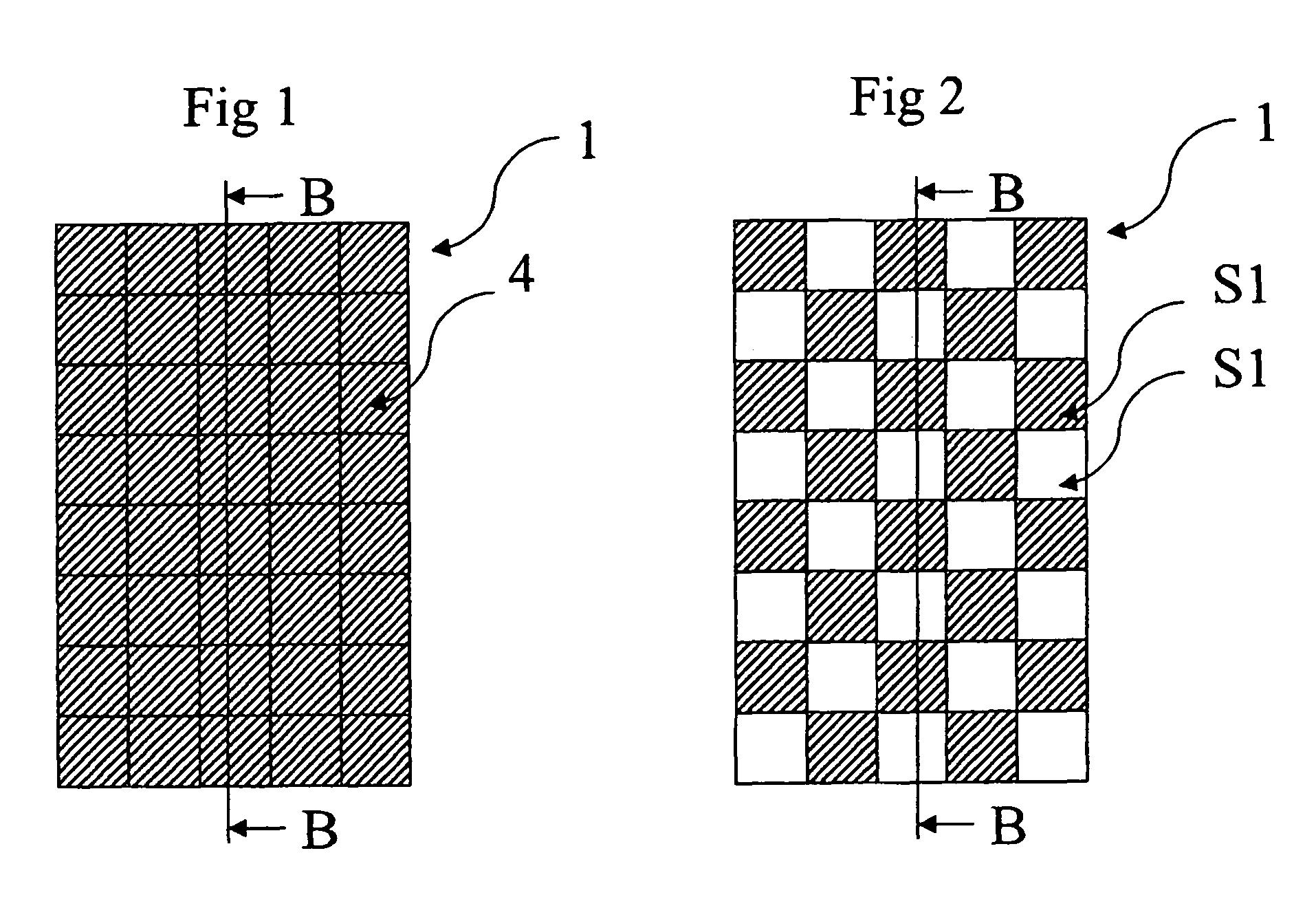
[0093]Two plies weave fabrics with squared pockets of different sizes were prepared using the same materials as in Example 2. The two plies were woven together by alternating them so as to obtain a chess design, as shown in FIG. 2, where the same side of two adjacent pockets is alternately made of the two different separate single plies. The fabric was woven according to the construction depicted in FIG. 6.

[0094]Three weave fabrics having closed square pockets of 8×8, 16×16 and 32×32 mm, respectively were prepared. The three fabrics had 42 ends / cm (warp) (21 ends / cm for each ply), 48 weft / cm (weft) (24 ends / cm for each ply) and a specific weight of 200 g / m2. The same physical tests as in Example 1 were carried out on the three fabrics with exception of the electric arc testing according to ASTM F1959.

[0095]The fabrics were tested both as single layer (Fabric in Table 3) and as the outershell of the multilayer structure as in Example 1 (Garment in Table 3).

[0096]The results are given...


PUM

PropertyMeasurementUnit
pocket sizeaaaaaaaaaa

Abstract

The present invention relates to a heat, flame, and electric arc resistant fabric (1) for use as single or outer layer of protective garments. The fabric (1) of the invention comprises at least two separate single plies which are assembled together at predefined positions so as to build pockets (4). The fabric (1) of the invention is made of materials independently chosen from the group consisting of aramid fibers and filaments, polybenzimidazol fibers and filaments, polyamidimid fibers and filaments, poly(paraphephenylene benzobisaxazole) fibers and filaments, phenol-formaldehyde fibers and filaments, melamine fibers and filaments, natural fibers and filaments, synthetic fibers and filaments, artificial fibers and filaments, glass fibers and filaments, carbon fibers and filaments, metal fibers and filaments, and composites thereof. Due to its peculiar structure, the fabric (1) according to the present invention can have a specific weight which is considerably lower than that of known fabrics having comparable mechanical and thermal properties.

Description

BACKGROUND OF THE INVENTION[0001]1. Field of the Invention[0002]The invention relates to a heat, flame and electric arc resistant fabric for use as single or outer layer of protective garments.[0003]2. Description of Related Art[0004]A garment protecting against heat, flame and electric arc is usually very heavy because the mass and the thickness of the garment itself are normally the main factors conferring protection. The wearer of such a garment, like for example the firefighter, is therefore limited in his movements and undergoes heat stress so that the overall wear comfort strongly decreases. In the last twenty years, attempts have continuously been made to develop new materials in order to improve the wear comfort of such protective garments. For example, lighter but more voluminous insulating materials have been developed for this purpose. These materials confer more lightness to the final protective garment but they might affect the respiratory activities of the wearer due t...

Claims


Application Information

Patent Timeline
Patent Type & Authority Patents(United States)
IPC IPC(8): D03D11/00D03D15/00A41D31/00D03D15/12
CPCA41D31/0027A41D31/0072D03D15/12D03D11/00D10B2331/021A41D31/085A41D31/265Y10T442/2221Y10T442/3293Y10T442/3179Y10T442/2213Y10T442/3992Y10T442/3472Y10T442/3317D03D15/513A41D31/00
Inventor BADER, YVESCAPT, ANDREDOTSCH, THOMAS
Owner DUPONT SAFETY & CONSTR INC
Why Eureka
Try Eureka