Liquid ejecting apparatus

a technology of liquid ejecting apparatus and nozzle, which is applied in the direction of measuring apparatus components, instruments, printing, etc., can solve problems such as nozzle blockage, and achieve the effect of miniaturizing the apparatus and reducing the number of components

Active Publication Date: 2013-06-04
SEIKO EPSON CORP
View PDF6 Cites 2 Cited by
  • Summary
  • Abstract
  • Description
  • Claims
  • Application Information

AI Technical Summary

Benefits of technology

[0006]An advantage of some aspects of the invention is to provide a liquid ejecting apparatus capable of suppressing the blockage of the nozzle that ejects liquid having a large specific weight.
[0008]According to the configuration, the liquid ejecting head is disposed so that the nozzle opens facing the direction higher than the horizontal direction. As a result, even in liquid which contains the metallic particles, and thus settling easily occurs, it is possible to suppress the settled metallic particles from being deposited in the vicinity of an opening of the nozzle. Thus, the blockage of the nozzle can be suppressed.
[0010]In general, a liquid that contains titanium oxide as a pigment has a specific weight higher than liquid containing pigments of other types. For that reason, in liquid containing titanium oxide, settling occurs more easily. Thus, according to the configuration, since the nozzle opens facing the direction higher than the horizontal direction, even in the case of ejecting liquid that contains titanium oxide and has the large specific weight, it is possible to suppress the titanium oxide from being deposited in the vicinity of the opening of the nozzle. That is, even in liquid which has a high content of the metallic particle per unit volume of liquid and has the large specific weight, the blockage of the nozzle is suppressed, whereby liquid can be satisfactorily ejected.
[0012]According to the configuration, by continuously ejecting liquid from the plurality of nozzles, an area to which liquid is attached is continuously formed on the target. Thus, even when some nozzles of the plurality of nozzles are blocked which makes it impossible to satisfactorily eject liquid, influence on picture quality can be reduced.
[0014]According to the configuration, by attaching the liquid containing the metallic particles with respect to the liquid attachment area, it is possible to perform a desired recording with respect to the target regardless of the type of the target. That is, for example, even when the recording is performed with respect to a transparent target having excellent light permeability, a desired coloring of the recording material can be obtained by attaching the metallic particles to reduce the light permeability.
[0016]According to the configuration, by pressing out the liquid from the nozzles which open facing the direction higher than the horizontal direction, thereby performing the cleaning of the nozzles, an amount of liquid to be consumed can be reduced, as compared to a case where, for example, liquid in the nozzle is absorbed to perform the cleaning. As a result, the number of components can be reduced and the apparatus can be miniaturized, without needing to provide a configuration such as a cap for receiving liquid discharged due to the cleaning or a tank for storing waste liquid.

Problems solved by technology

For that reason, as in the printer of JP-A-2005-153507, in a case where the printing is performed with respect to the recording medium situated at a lower part of a vertical direction of the recording head, there is a concern that the pigment settles in the vicinity of a nozzle situated at the lower part with respect to the recording head, which causes blockage in the nozzle.

Method used


Image

  • Liquid ejecting apparatus
  • Liquid ejecting apparatus
  • Liquid ejecting apparatus

Examples


first embodiment

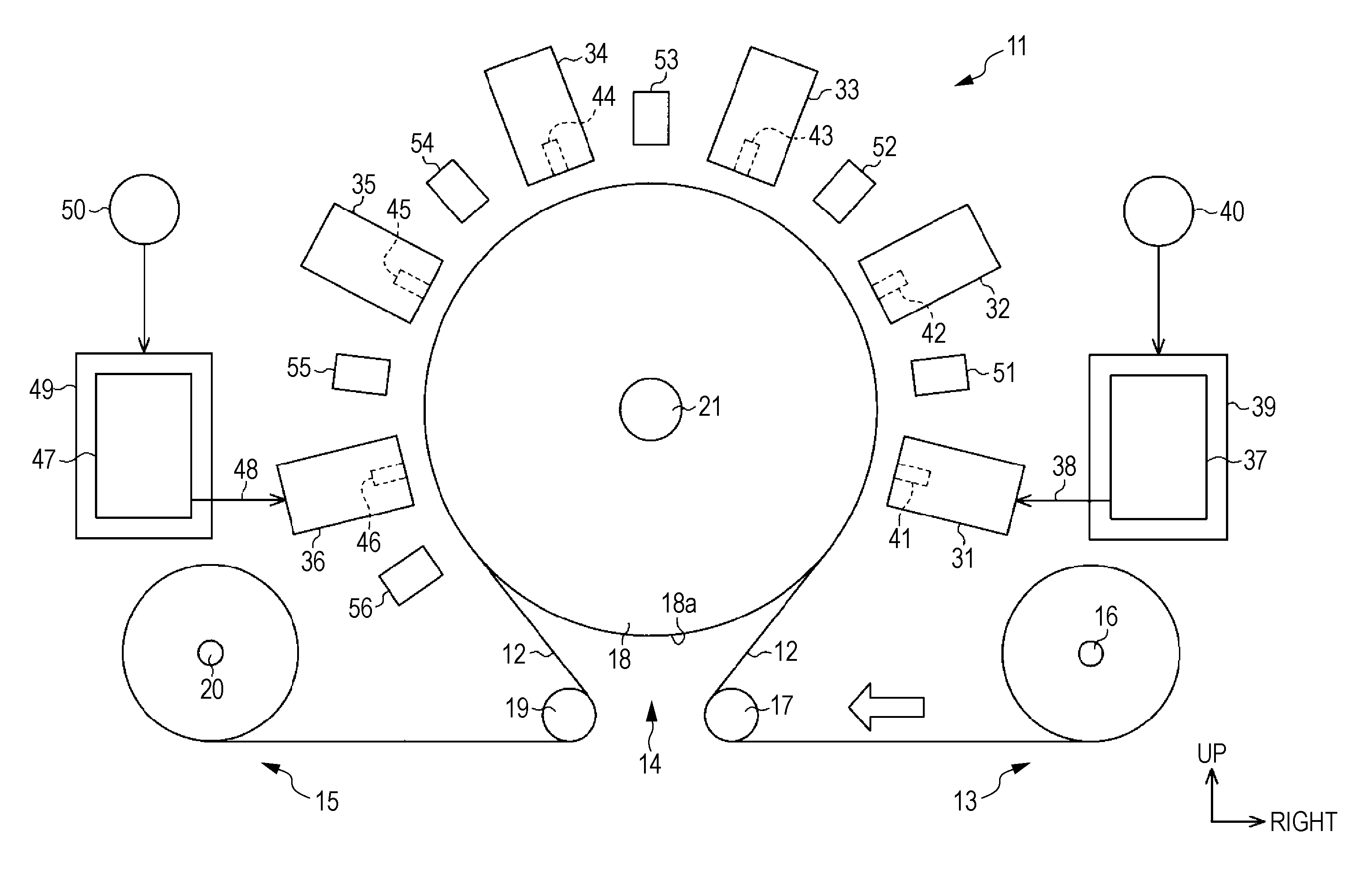
[0021]Hereinafter, a first embodiment embodying in an ink jet type printer (hereinafter, also referred to as “printer”) of the invention will be described based on FIGS. 1 and 2. In addition, in the following description of the specification, “up and down direction” and “left and right direction” are shown on the basis of a direction shown by arrows in FIG. 1.

[0022]As shown in FIG. 1, on a printer 11 as a liquid ejecting apparatus, an unwind portion 13 for unwinding a film 12 which is an elongated target, a printing portion 14 for printing (recording) the film 12, and a windup portion 15 for winding up the printed film 12.

[0023]That is, in a transport direction of the film 12 shown by a white arrow in FIG. 1, the unwind portion 13 is disposed at a position near a right side which is the upstream side, and the windup portion 15 is disposed at a position near a left side which is the downstream side. In addition, the printing portion 14 is disposed at a position between the unwind por...

second embodiment

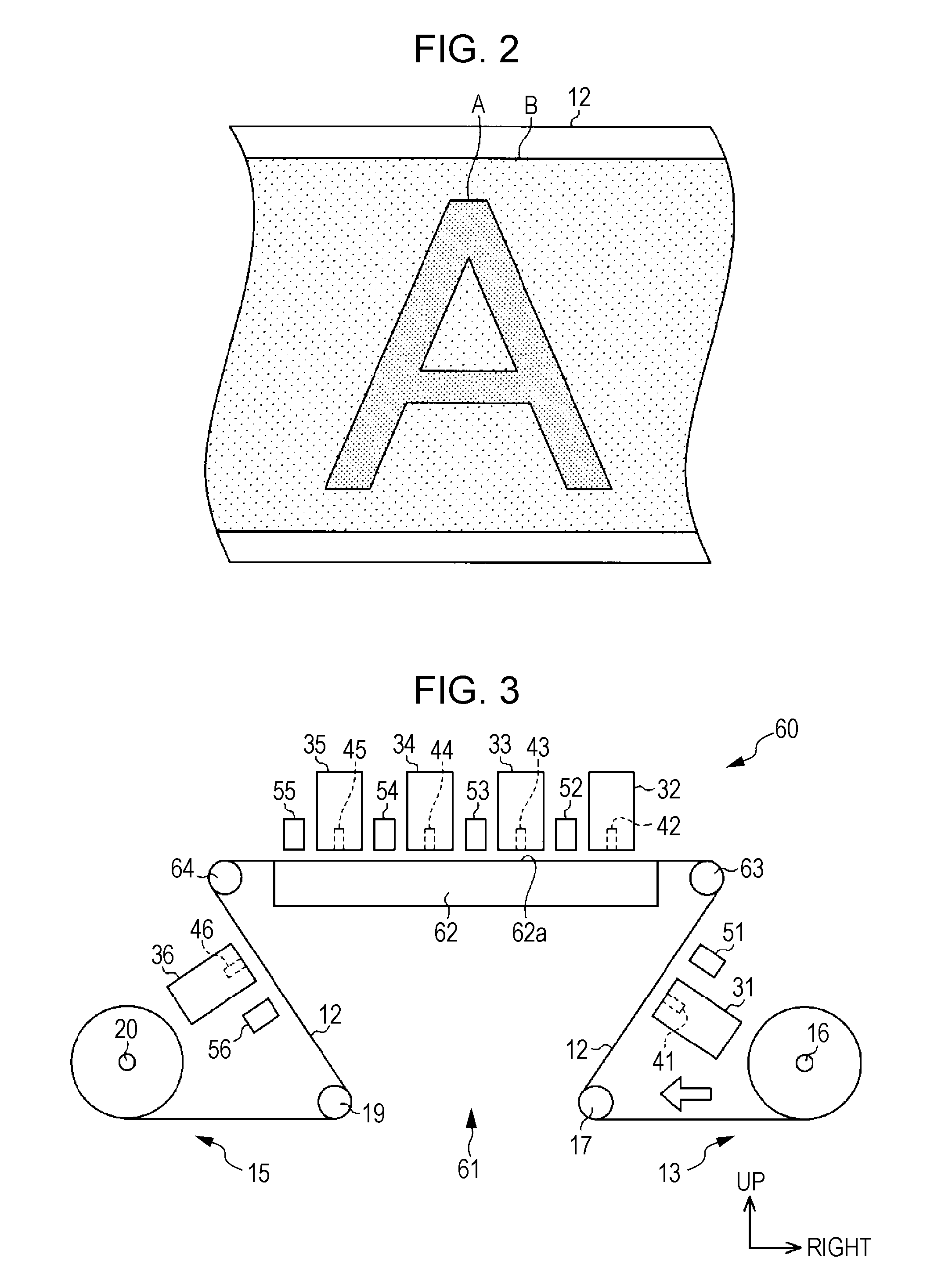
[0059]Next, a second embodiment of the invention will be described based on FIG. 3. In addition, the second embodiment is different from the first embodiment only in that the configuration of the printing portion is changed, and other configurations are the same, thus the same constituents are denoted by the same reference numerals and the detailed repetition description will be omitted.

[0060]As shown in FIG. 3, on the printing portion 61 of the printer 60, a platen 62 having a planar shape capable of supporting the film 12 is provided, and a third roller 63 and a fourth roller 64, which pinch the platen 62 therebetween and are opposed to each other in the left and right direction, are provided.

[0061]In addition, the film 12 unwound from the unwind portion 13 is sequentially wound around the first roller 17, the third roller 63, the fourth roller 64, and the second roller 19, and the transport direction of the film 12 shown by the white arrow in FIG. 3 is changed, the film 12 is wou...


PUM


Abstract

A liquid ejecting apparatus includes a liquid ejecting head which ejects liquid containing metallic particles from a nozzle with respect to a target, the liquid ejecting head being disposed so that the nozzle opens facing a direction higher than a horizontal direction, and ejects the liquid from the nozzle facing the direction higher than the horizontal direction, thereby attaching the liquid to the target.

Description

BACKGROUND[0001]1. Technical Field[0002]The present invention relates to, for example, a liquid ejecting apparatus such as an ink jet type printer.[0003]2. Related Art[0004]Hitherto, a liquid ejecting apparatus for ejecting liquid with respect to a target, an ink jet type printer (hereinafter, also referred to as “printer”) is widely known. The printer is adapted to perform printing to a recording medium as the target by ejecting ink (liquid), which is supplied to a recording head (a liquid ejecting head), from a nozzle formed in the recording head. In addition, in terms of this type of printer, recently, for example, as described in JP-A-2005-153507, there is a printer in which white ink is attached to a surface of the recording medium to perform a foundation treatment and a color ink (the recording material) including a color material is attached to an area, in which the foundation treatment has been performed, to perform the printing.[0005]However, the white ink generally contain...

Claims


Application Information

Patent Timeline
Patent Type & Authority Patents(United States)
IPC IPC(8): B41J2/015
CPCB41J2/14B41J2/16526B41J2/2114B41J2/2117
Inventor SHIMIZU, KAZUTOSHIAKATSUKA, YASUSHIMASUDA, NORIHIROFUJISAWA, KAZUTOSHI
Owner SEIKO EPSON CORP
Why Eureka
Try Eureka