Connector for seismic cable

a technology of seismic cable and connector, which is applied in the direction of coupling device connection, vessel construction, instruments, etc., can solve the problems of creating noise and risk of injury to personnel that may be in the vicinity of the cabl

Active Publication Date: 2011-04-26
APPLIED FIBER MFG +1
View PDF24 Cites 47 Cited by
  • Summary
  • Abstract
  • Description
  • Claims
  • Application Information

AI Technical Summary

Problems solved by technology

Generally, the method for detection and recording of seismic signals is similar on land and in marine environments; however, marine environments present unique challenges presented by the body of water overlying the earth's surface.
In some applications, the connectors 20 may be made of or include a metallic material, which may create noise during the seismic survey.
Further, the ring-like or hook-like members 55 create the risk of injury to personnel that may be in the vicinity of the cable, such as during a seismic sensor unit coupling and decoupling procedure.
The buoyancy of the cable 1 makes the sections between the connectors 20 vulnerable to currents and / or hydrodynamic forces, which may alter the fall or cause a drift of the mainline cable.

Method used


Image

  • Connector for seismic cable
  • Connector for seismic cable
  • Connector for seismic cable

Examples


Embodiment Construction

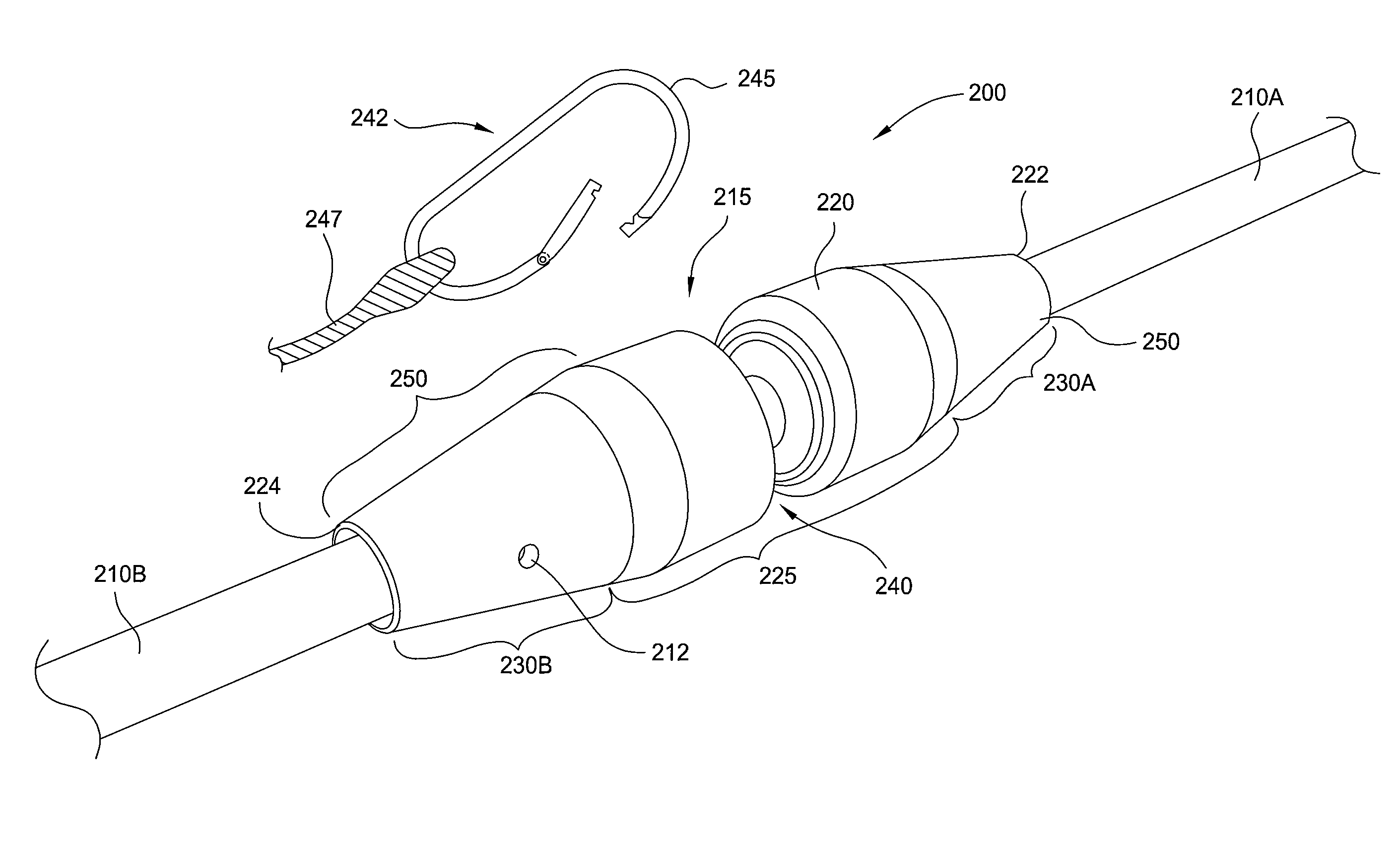
[0033]Embodiments described herein generally provide methods and apparatus for coupling at least two free ends of a seismic cable in a connection that provides a connection point for another device or object. While embodiments described herein are exemplarily described in reference to a seismic cable, some embodiments may be used in other industries or applications.

[0034]FIG. 2A is a perspective view of a portion of one embodiment of a section 200 of a seismic cable. The section 200 of seismic cable includes a first cable segment 210A and a second cable segment 210B having ends coupled together by a connector 215. The connector 215 includes a body 220 having a first end 222 and a second end 224 opposing the first end 222. The first cable segment 210A and second cable segment 210B have respective ends that terminate at the body 220. The body 220 of the connector 215 also includes at least three coupling sections, shown as a central coupling section 225, a first coupling section 230A ...


PUM


Abstract

A method and apparatus for a seismic cable is described. The apparatus includes a plurality of cable segments comprising at least a first cable segment and a second cable segment coupled by a connector. The connector comprises a cylindrical body having a first diameter, a portion of the body having a second diameter that is smaller than the first diameter and centrally positioned between opposing ends of the body, a first coupling section having a terminating end of the first cable segment anchored therein, and a second coupling section having a terminating end of the second cable segment anchored therein, at least a portion of the first and second coupling sections being rotatably coupled to respective ends of the body, wherein the connector isolates the first cable segment from the second cable segment. A method of deployment and retrieval of the seismic cable is also described.

Description

BACKGROUND OF THE INVENTION[0001]1. Field of the Invention[0002]Embodiments described herein relate to methods and apparatus for a seismic cable. More particularly, embodiments described herein relate to a cable connector for coupling sections of a seismic cable.[0003]2. Description of the Related Art[0004]Seismic exploration operations generally utilize a seismic energy source to generate an acoustic signal that propagates into the earth. The acoustic signal is partially reflected by subsurface seismic reflectors in the earth, which may include interfaces between subsurface lithologic or fluid layers that may be characterized by different elastic properties. The reflected signals are detected and recorded by seismic receiver units located at or near the surface of the earth, thereby generating a seismic survey of the subsurface environment. The recorded signals, or seismic energy data, can then be processed to yield information relating to the lithologic subsurface formations, iden...

Claims


Application Information

Patent Timeline
Patent Type & Authority Patents(United States)
IPC IPC(8): G01V1/52G01V1/38
CPCG01V1/201H01R13/523H01R39/643H01R13/622H01R13/533
Inventor THOMPSON, JAMES N.MARC, ETIENNECAMPBELL, RICHARDNYE, RICHARD E.
Owner APPLIED FIBER MFG
Why Eureka
Try Eureka