
Systems and methods for stabilization of bone structures

a bone structure and system technology, applied in the field of spinal disorders and pain, can solve the problems of affecting the ability of a spinal motion segment to properly function, eventual deterioration or disorder, and debilitating pain, so as to reduce long-term complications, preserve the natural biomechanics and motion, and reduce pain.

Inactive Publication Date: 2011-05-03
EXACTECH INC
View PDF428 Cites 104 Cited by
  • Summary
  • Abstract
  • Description
  • Claims
  • Application Information

AI Technical Summary

Benefits of technology

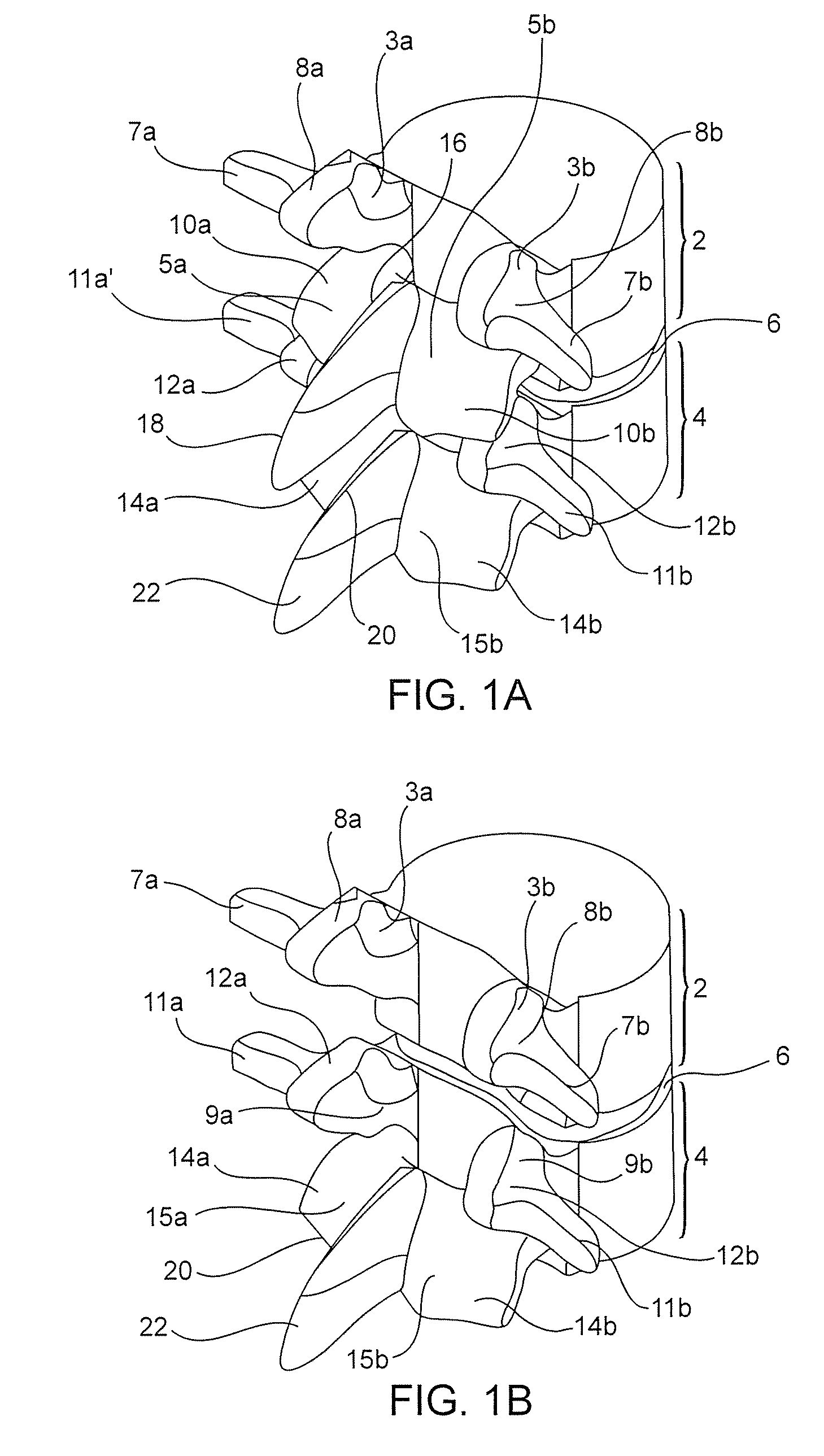
[0012]The current invention provides an enhanced dynamic rod system that may be disposed between two pedicle screws, two crossbars, a combination of a pedicle screw and a crossbar, or two other spinal devices, that can provide a patient with spinal support and freedom of movement that is very close to that of a normally-functioning healthy spine. The dynamic nature allows controlled flexibility, motion, and movement, between two vertebral segments being stabilized. A high degree of the natural biomechanics and motion are preserved. In addition, pain is reduced and long-term complications are reduced. The system also avoids unnecessary stresses placed on neighboring vertebral segments, as are seen in standard fusion techniques, which cause accelerated degeneration of vertebral structures and associated pain.
[0015]The current invention allows convenient installation and removal in a patient. The ease of installation and removal in turn allows embodiments to be removed if further degeneration occurs, to be replaced with a fixed rod installed into the bone screws already installed in the pedicles. This allows the surgeon a revision strategy for the patient between the different systems.

Problems solved by technology

Traumatic, inflammatory, metabolic, synovial, neoplastic and degenerative disorders of the spine can produce debilitating pain that can affect a spinal motion segment's ability to properly function.
Often, a disorder in one location or spinal component can lead to eventual deterioration or disorder, and ultimately, pain in another.
However, fusion is only as good as the ability to restore disc height to relieve the pain by taking pressure off the nerves, nerve roots, and / or articulating surfaces—i.e., facet joints and end plates of the vertebral bodies.
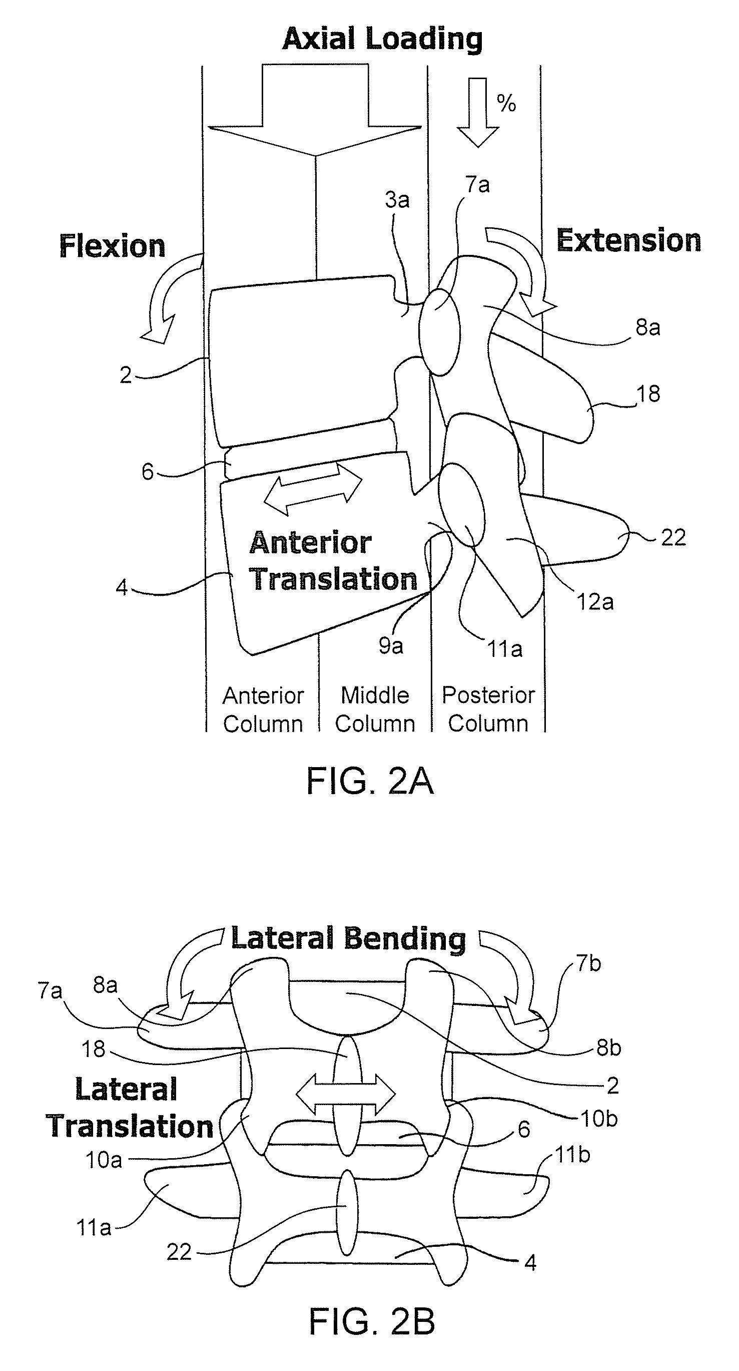
While spine fusion generally helps to eliminate certain hypes of pain, it has been shown to decrease function by limiting the range of motion for patients in flexion, extension, rotation and lateral bending.
Furthermore, fusion creates increased stresses on adjacent non-fused motion segments and accelerated degeneration of the motion segments.
Additionally, pseudarthrosis (resulting from an incomplete or ineffective fusion) may not provide stability of the degenerative spine or the expected pain-relief for the patient.
Also, the device(s) used for fusion, whether artificial or biological, may migrate out of the fusion site creating significant new problems for the patient.
In addition, fusion of the spine causes the increased transfer of stresses to the anatomical structures above and below the site of fusion.
Unfortunately, the currently available artificial discs do not adequately address all of the mechanics of motion for the spinal column.
Because the interspinous spacers involve attachment to the spinous processes, use of these types of systems is limited to applications where the spinous processes are uncompromised and healthy.
While this system is able to provide load sharing and restoration of disc height, because it is so rigid, it is not effective in preserving the natural motion of the spinal segment into which it is implanted.

Method used


Image

  • Systems and methods for stabilization of bone structures
  • Systems and methods for stabilization of bone structures
  • Systems and methods for stabilization of bone structures

Examples


Embodiment Construction

[0037]Before the present invention are described, it is to be understood that this invention is not limited to particular embodiments described, as such may, of course, vary. It is also to be understood that the terminology used herein is for the purpose of describing particular embodiments only, and is not intended to be limiting, since the scope of the present invention will be limited only by the appended claims.

[0038]Where a range of values is provided, it is understood that each intervening value, to the tenth of the unit of the lower limit unless the context clearly dictates otherwise, between the upper and lower limits of that range is also specifically disclosed. Each smaller range between any stated value or intervening value in a stated range and any other stated or intervening value in that stated range is encompassed within the invention. The upper and lower limits of these smaller ranges may independently be included or excluded in the range, and each range where either...


PUM


Abstract

A dynamic bone stabilization system is provided. The system may be placed through small incisions and tubes. The system provides systems and methods of treating the spine, which eliminate pain and enable spinal motion, which effectively mimics that of a normally functioning spine. Methods are also provided for stabilizing the spine and for implanting the subject systems.

Description

CROSS-REFERENCE[0001]This application is a continuation-in-part of prior-filed U.S. Non-Provisional patent application Ser. No. 11 / 436,407, filed May 17, 2006, which is a continuation-in-part of U.S. Non-Provisional patent application Ser. No. 11 / 033,452 filed Jan. 10, 2005, which is a continuation-in-part of U.S. Non-Provisional patent application Ser. No. 11 / 006,495 filed Dec. 6, 2004, which is a continuation-in-part of U.S. Non-Provisional patent application Ser. No. 10 / 970,366, filed on Oct. 20, 2004; this application is also a continuation-in-part of prior-filed U.S. Non-Provisional patent application Ser. No. 11 / 362,366, filed Feb. 23, 2006, which is a continuation-in-part of U.S. Provisional Patent Application Ser. No. 60 / 701,660, filed Jul. 22, 2005, all of which are incorporated herein by reference in their entirety and are assigned to the assignee of the present invention.FIELD OF THE INVENTION[0002]The present invention is directed towards the treatment of spinal disorder...

Claims


Application Information

Patent Timeline
Patent Type & Authority Patents(United States)
IPC IPC(8): A61B17/70
CPCA61B17/7004A61B17/7005A61B17/7023A61B17/7037A61B17/7031A61B17/7032A61B17/7026A61B17/7028
Inventor REGLOS, JOEY CAMIAALTARAC, MOTIHAYES, STANLEY KYLETEBBE, SHAWNKIM, DANIEL H.FLAHERTY, J. CHRISTOPHER
Owner EXACTECH INC
Learn More