Plane light source and LCD backlight unit having the same

a backlight unit and light source technology, applied in lighting and heating apparatus, instruments, lighting support devices, etc., can solve the problems of low response speed, low color reproducibility, environmental contamination, etc., and achieve the effect of increasing efficiency and reducing the number of light emitting devices

Active Publication Date: 2011-05-10
SAMSUNG ELECTRONICS CO LTD
View PDF11 Cites 436 Cited by
  • Summary
  • Abstract
  • Description
  • Claims
  • Application Information

AI Technical Summary

Benefits of technology

[0013]An aspect of the present invention provides a plane light source that reduces the number of light emitting devices and increases efficiency by optimizing the arrangement and pitch of a plurality of light emitting devices, and an LCD backlight unit having the same.

Problems solved by technology

For this reason, the CCFL may cause environmental contamination, has low response speed and lower color reproducibility, and may not lead to a reduction in size, thickness, and weight of an LCD panel.
However, such an arrangement requires a larger number of LEDs used to cover the same light emitting area than necessary.

Method used


Image

  • Plane light source and LCD backlight unit having the same
  • Plane light source and LCD backlight unit having the same
  • Plane light source and LCD backlight unit having the same

Examples


Embodiment Construction

[0034]Exemplary embodiments of the present invention will now be described in detail with reference to the accompanying drawings.

[0035]The invention may however be embodied in many different forms and should not be construed as limited to the embodiments set forth herein. Rather, these embodiments are provided so that this disclosure will be thorough and complete, and will fully convey the scope of the invention to those skilled in the art. In the drawings, the shapes and dimensions may be exaggerated for clarity, and the same reference numerals will be used throughout to designate the same or like components.

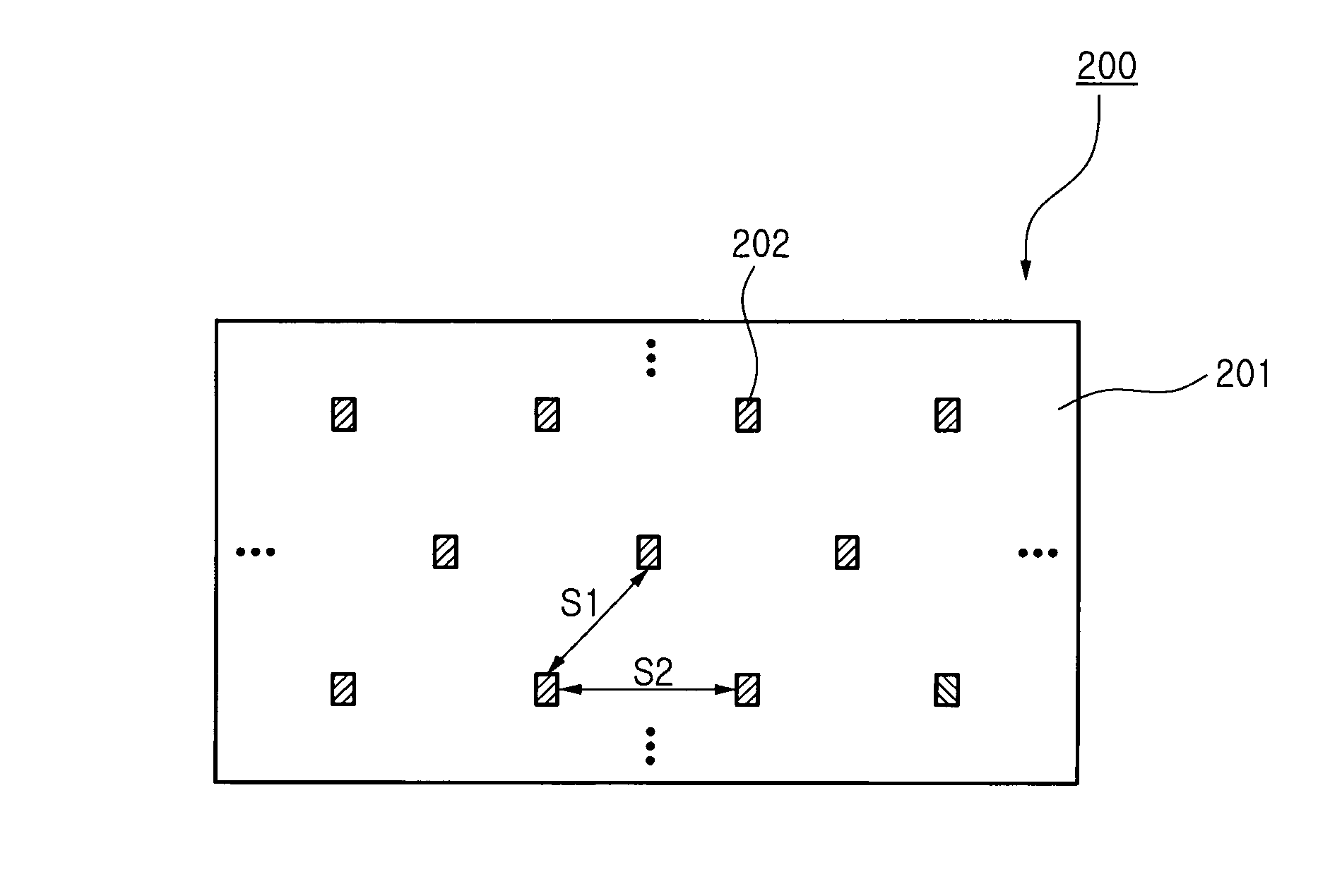
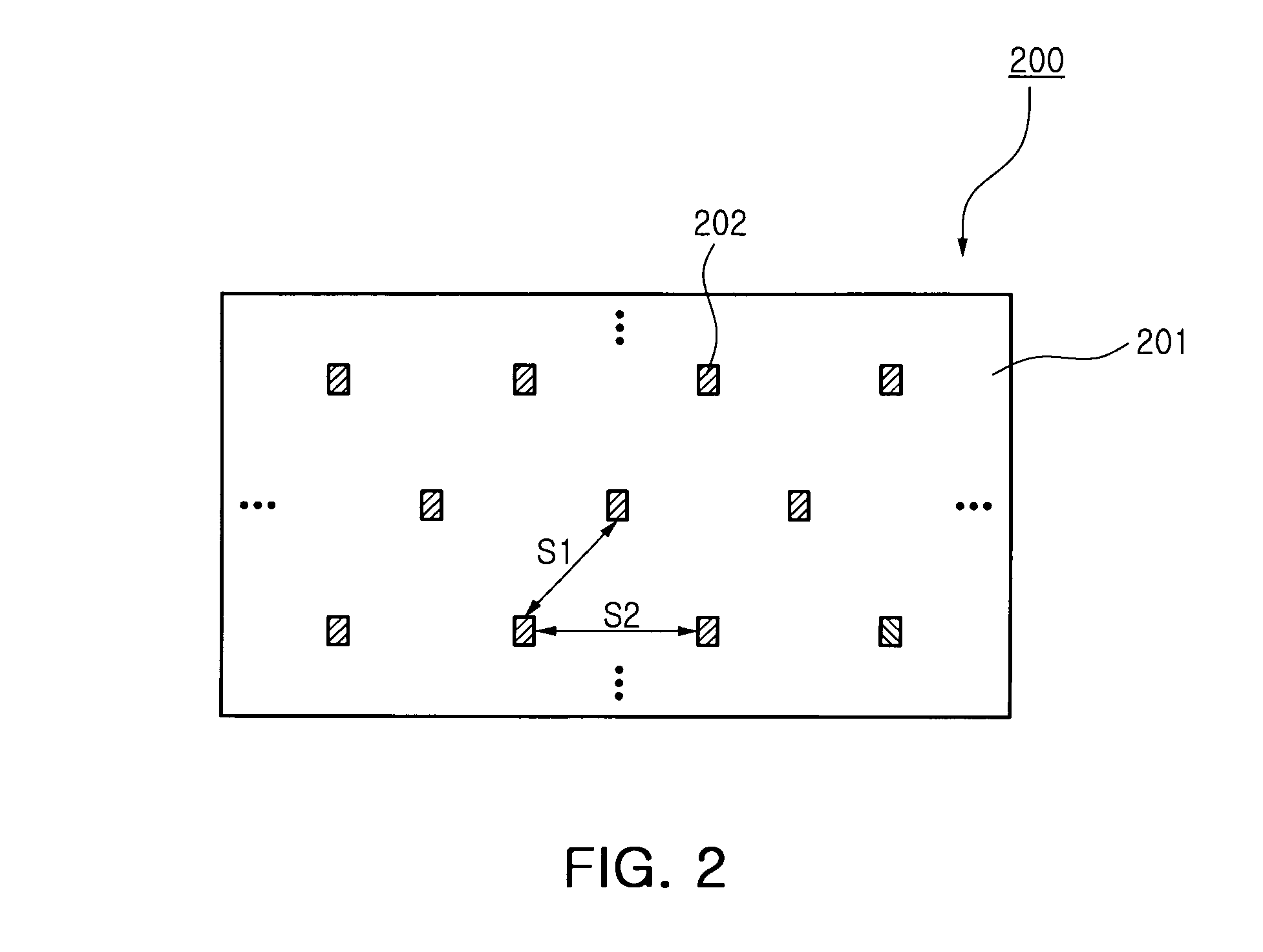
[0036]FIG. 2 is a schematic view illustrating an arrangement of light emitting devices in a plane light source according to an exemplary embodiment of the invention.

[0037]A plane light source 200 according to this embodiment of the invention includes a plurality of light emitting devices 202 that are arranged at a substrate 201.

[0038]The light emitting devices 202 are arranged ...


PUM

PropertyMeasurementUnit
angleaaaaaaaaaa
orientation angleaaaaaaaaaa

Abstract

There are provided a plane light source and an LCD backlight unit having the same. A plane light source having a plurality of light emitting devices arranged in a light emitting device matrix having rows and columns at a substrate according to an aspect of the invention includes a first matrix having a plurality of light emitting devices arranged in rows and columns; and a second matrix having a plurality of light emitting devices arranged in rows and columns, each of the light emitting devices located within a quadrangle formed by four neighboring light emitting devices included in the first matrix, wherein a pitch S between one light emitting device included in the light emitting device matrix and another light emitting device most adjacent to the one light emitting device satisfies the following equation to obtain uniform luminance distribution at a position distant from a light emitting surface of the light emitting device by an optical length l,S≤l2×tan⁡(θ2+α),Equationwhere −π / 18≦α≦π / 18 is satisfied, and θ is an orientation angle of the light emitting device.

Description

CROSS-REFERENCE TO RELATED APPLICATIONS[0001]This application claims the priority of Korean Patent Application No. 2007-0046845 filed on May 15, 2007, in the Korean Intellectual Property Office, the disclosure of which is incorporated herein by reference.BACKGROUND OF THE INVENTION[0002]1. Field of the Invention[0003]The present invention relates to a plane light source and an LCD backlight unit having the same, and more particularly, to a plane light source that increases efficiency and reduces the number of light emitting devices by optimizing the arrangement and pitch of a plurality of light emitting devices, and an LCD backlight unit having the same.[0004]2. Description of the Related Art[0005]In general, cold cathode fluorescent lamps (CCFLs) that are used as light sources of liquid crystal displays (LCDs) according to the related art use mercury gas. For this reason, the CCFL may cause environmental contamination, has low response speed and lower color reproducibility, and may...

Claims


Application Information

Patent Timeline
Patent Type & Authority Patents(United States)
IPC IPC(8): G02F1/1333
CPCG02F1/133603F21V21/00F21V11/00G02F2001/133613G02F1/133613G02F1/1335
Inventor JEONG, YOUNG JUNE
Owner SAMSUNG ELECTRONICS CO LTD
Why Eureka
Try Eureka