
Torsion coil spring and sliding type mobile terminal equipped therewith

a technology of mobile terminals and rotating coils, which is applied in the direction of mechanical equipment, wireless communication, wound springs, etc., can solve the problems of inability to maximize the size of the display part, the hinge part occupies a large space, and the display part and the operation part are kept. , good portability and operability

Inactive Publication Date: 2011-05-10
SHARP KK
View PDF37 Cites 16 Cited by
  • Summary
  • Abstract
  • Description
  • Claims
  • Application Information

AI Technical Summary

Benefits of technology

[0014]The present invention has been made in view of these circumstances. It is a first object of the present invention to provide a torsion coil spring that can be arranged in a thin space and is space-saving at the same time, with reduced height and outside diameter for the coil part.
[0015]Further, it is a second object of the present invention to devise the structure of a signal line that electrically connects the first housing and the second housing to one another and a torsion coil spring that aids the sliding of the first housing in order to facilitate the wiring of the signal line and thus to prevent the signal line from hindering the sliding operation, thereby increasing the degree of sliding.

Problems solved by technology

A straight type mobile terminal has a limited area that appears on the surface, and the display part and the operation part must be provided on the limited surface, making it impossible to secure sufficient space for the size of the display part.
Consequently, the hinge part occupies much space on the display part, which serves as a hindrance to securing a place for the display part to occupy.
Thus, it is occasionally impossible to maximize the size of the display part in the straight type mobile terminal and the folding type mobile terminal.
However, the torsion coil springs disclosed in Japanese Unexamined Patent Application Publication Nos. 2005-174919 and 2006-206230 involve many times of winding to raise the height of the coil part, thereby disabling the springs to be provided in a thin space.
In this case, there was such a problem that in order to obtain a necessary biasing power, the outside diameter of the coil part increases and thus takes up much space for installation, making it difficult to provide the spring in an biasing structure of a compact mobile terminal such as a mobile phone.
Further, in a sliding type mobile terminal such as what is shown in Japanese Unexamined Patent Application Publication No. 2006-165854, unless wiring of a signal line (including a flexible substrate) to connect the first housing and the second housing is properly carried out, it may impede sliding operation.
As a result, there were problems in which a smooth sliding operation was not possible or the degree of sliding was reduced to prevent the signal line from getting entwined, thus causing the operation part to become small.

Method used


Image

  • Torsion coil spring and sliding type mobile terminal equipped therewith
  • Torsion coil spring and sliding type mobile terminal equipped therewith
  • Torsion coil spring and sliding type mobile terminal equipped therewith

Examples


Embodiment Construction

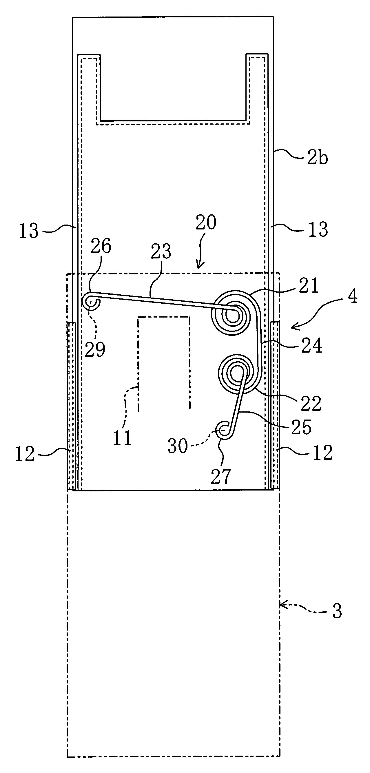
4 in which the first housing at a mid-position of sliding movement is shown.

[0055]FIG. 6 is a diagram equivalent to FIG. 2 in which the first housing at the mid-position of the sliding movement is shown.

[0056]FIG. 7 is a diagram equivalent to FIG. 4 in which the first housing in the midst of sliding movement is shown.

[0057]FIG. 8 is a diagram equivalent to FIG. 2 in which the first housing in the midst of sliding movement is shown.

[0058]FIG. 9 is a diagram equivalent to FIG. 4 in which the first housing superposed on a second housing is shown.

[0059]FIG. 10 is a diagram equivalent to FIG. 2 in which the first housing superposed on the second housing is shown.

[0060]FIG. 11 is a perspective view of the torsion coil spring.

[0061]FIG. 12 is a plan view of the torsion coil spring.

[0062]FIG. 13 is a side view of the torsion coil spring.

[0063]FIG. 14 is a diagram showing a first housing of a sliding type mobile terminal according to a modified example of an embodiment of the present inventi...


PUM


Abstract

A torsion coil spring has first and second coil parts and first to third straight line parts. One end of the first coil part is continued to a first straight line part, while the other end is continued to one end of a second straight line part. The other end of the second straight line part is continued to one end of a second coil part, and the other end of the second coil part is continued to one end of the third straight line part. Also, a mobile terminal having a first housing slidably coupled to a second housing is provided. On the surface of the second housing, a pair of rail parts is provided extending in a sliding direction of the first housing. Between the rail parts, the torsion coil spring is provided for aiding sliding of the first housing on the rail parts of the second housing.

Description

[0001]This non-provisional application claims priority based on Patent Application Nos. 2006-344125 filed in Japan on Dec. 21, 2006, and 2006-344127 filed in Japan on Dec. 21, 2006, the entire contents of which are hereby incorporated by reference.BACKGROUND OF THE INVENTION[0002]1. Field of the Invention[0003]The present invention relates to, for example, a torsion coil spring used for mobile phones, mobile communication terminal, and the like in which a first housing and a second housing are slidably connected to one another, and to a sliding type mobile terminal equipped with the torsion coil spring.[0004]2. Description of the Related Art[0005]A torsion coil spring having stretching force in the torsional direction has hitherto been used.[0006]For example, in Japanese Unexamined Patent Application Publication No. 2005-174919, a torsion coil spring is used for electronic equipment having a battery pack or a housing part of dry cells. In this electronic equipment, the housing part ...

Claims


Application Information

Patent Timeline
Patent Type & Authority Patents(United States)
IPC IPC(8): H04M1/00
CPCH04M1/0237H01R35/02H01R2201/16H04B1/38
Inventor MIFUNE, MASAYUKIIMAI, KIMIAKI
Owner SHARP KK
Learn More