Method and apparatus for capacity on demand dynamic chunk allocation
a dynamic chunk and capacity technology, applied in the field of storage resource management, can solve the problems of write command failure, conventional storage resource management techniques fail to enable provision of extra capacity (adding new chunks) with short latency, and achieve the effect of short latency and short write command failure tim
- Summary
- Abstract
- Description
- Claims
- Application Information
AI Technical Summary
Benefits of technology
Problems solved by technology
Method used
Image
Examples
first embodiment
System Configuration
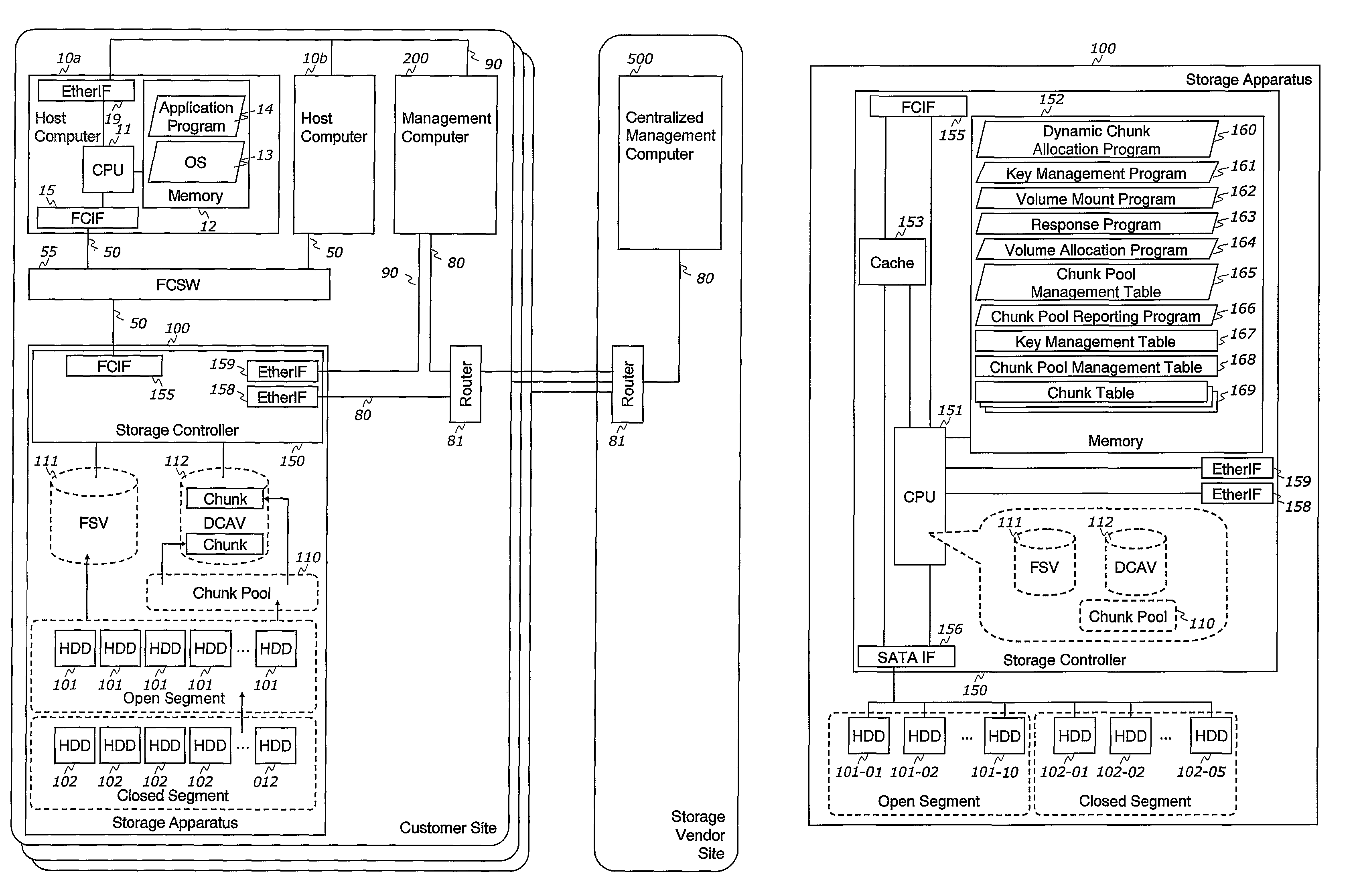
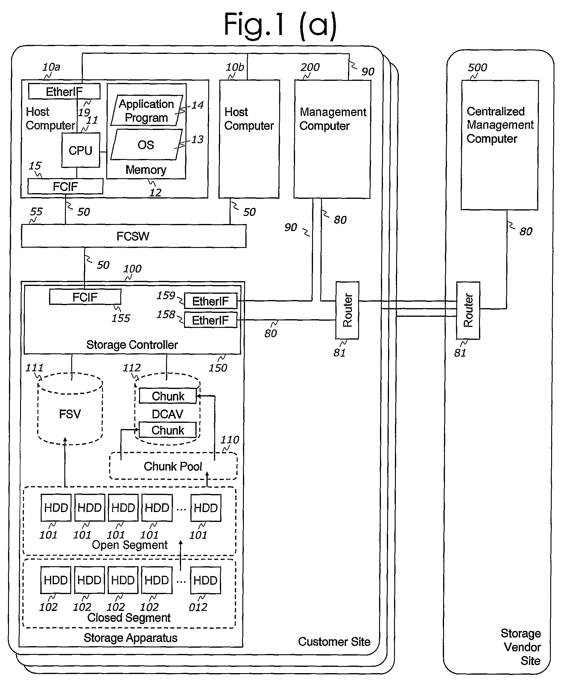
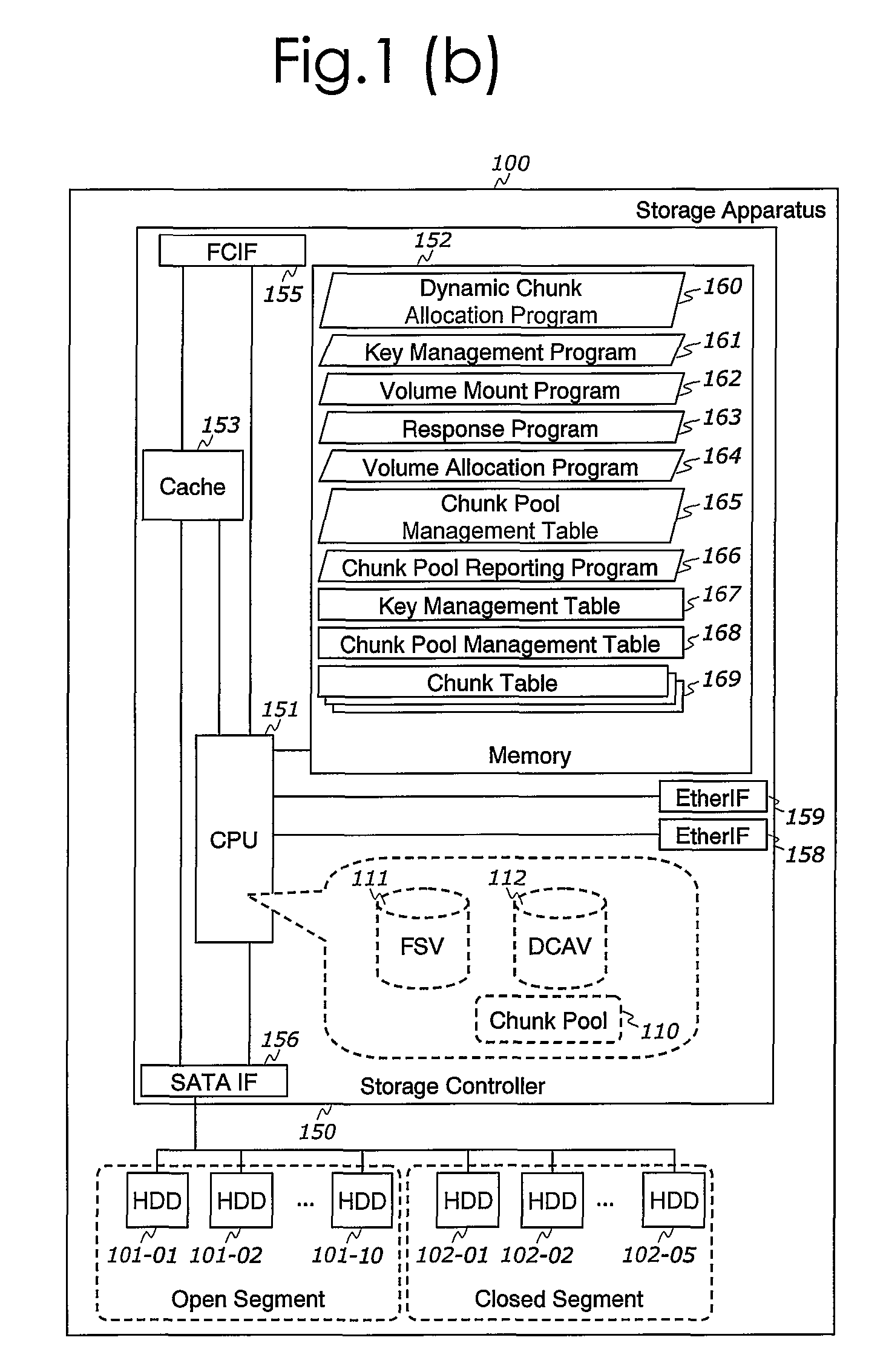
[0044]FIG. 1(a) illustrates an exemplary embodiment of the computerized storage system in which the techniques of this invention are applied. The computerized storage system of the aforesaid first embodiment includes:
Host Computer 10:
[0045]In an embodiment of the inventive technique, at least one host computer 10 is connected to the storage apparatus 100 via data network 50. In the embodiment shown in FIG. 1, two host computers 10a, 10b are so connected. The host computers 10 execute at least one operating system (OS) 13. As it will be appreciated by those of skill in the art, the present invention is not limited to any specific OS 13. Any suitable operating systems, such as Windows, Unix, Linux and the like may be employed as the OS 13. Also, an application 14 may be executed by the host computer 10 under the direction of the OS 13. Files and data for the OS 13 and the application 14 are stored in one or more storage volumes, which are provided by the storage ap...
second embodiment
Hierarchical System Configuration
[0123]FIG. 19 illustrates an exemplary embodiment of the information system in which another method of this invention can be applied. The description below will emphasize the differences between the first embodiment described above and the second embodiment. Specifically, in the second embodiment of the inventive system, two more storage apparatuses 100b and 100c are provided in addition to the storage apparatus 100a of the first embodiment, see FIG. 19. These three storage apparatuses are interconnected by a Fibre Channel switch 56, see FIG. 19. To this end, the storage apparatus 100a is provided with the FCIF 157a for connecting it to the other storage apparatuses. Likewise, the storage apparatus 100b is provide with the FCIF 157b connected to the Fibre Channel switch 56. Thus, the two storage apparatuses 100a and 100b are connected to the storage apparatus 100c via the FCSW 56.
[0124]In the second embodiment, the storage apparatus 100a incorporates...
third embodiment
System Configuration
[0143]FIG. 23 illustrates yet another exemplary embodiment of the information system in which the method of this invention can be applied. The difference between the second embodiment and the third embodiment will now be described in detail. Specifically, in the third embodiment, a storage apparatus 100d is located at the storage vendor site and not at the customer site as in the second embodiment. A remote data network 70 is provided for interconnecting the storage apparatus 100a in the customer site and the storage apparatus 100d in the storage vendor site. The remote data network 70 in the third embodiment is implemented using the Fibre Channel technology. However, the inventive concept is not limited to any specific networking system and other network interfaces, such as Ethernet and the like, can also be utilized.
[0144]To enable the remote data network 70, in the third embodiment, the two routers 71 are used. Also in the third embodiment, the storage apparat...
PUM
 Abstract
Description
Claims
Application Information
 - R&D
- Intellectual Property
- Life Sciences
- Materials
- Tech Scout
- Unparalleled Data Quality
- Higher Quality Content
- 60% Fewer Hallucinations
Browse by: Latest US Patents, China's latest patents, Technical Efficacy Thesaurus, Application Domain, Technology Topic, Popular Technical Reports.
© 2025 PatSnap. All rights reserved.Legal|Privacy policy|Modern Slavery Act Transparency Statement|Sitemap|About US| Contact US: help@patsnap.com


