Ransmission Capacity Allocation Method, Communications Network, and Network Resource Management Device

Inactive Publication Date: 2008-10-02
YAZAKI CORP
View PDF12 Cites 146 Cited by
  • Summary
  • Abstract
  • Description
  • Claims
  • Application Information

AI Technical Summary

Benefits of technology

[0007]The primary task in eliminating these problems is path discovery on the network. On Ethernet networks, as a result of the tree topology (including path topology), multiple paths are not generated, but network resources are wasted when flooding (frames being relayed to all the transmission links except for the input transmission

Problems solved by technology

On Ethernet networks, as a result of the tree topology (including path topology), multiple paths are not generated, but network resources a

Method used


Image

  • Ransmission Capacity Allocation Method, Communications Network, and Network Resource Management Device
  • Ransmission Capacity Allocation Method, Communications Network, and Network Resource Management Device
  • Ransmission Capacity Allocation Method, Communications Network, and Network Resource Management Device

Examples


embodiment 1

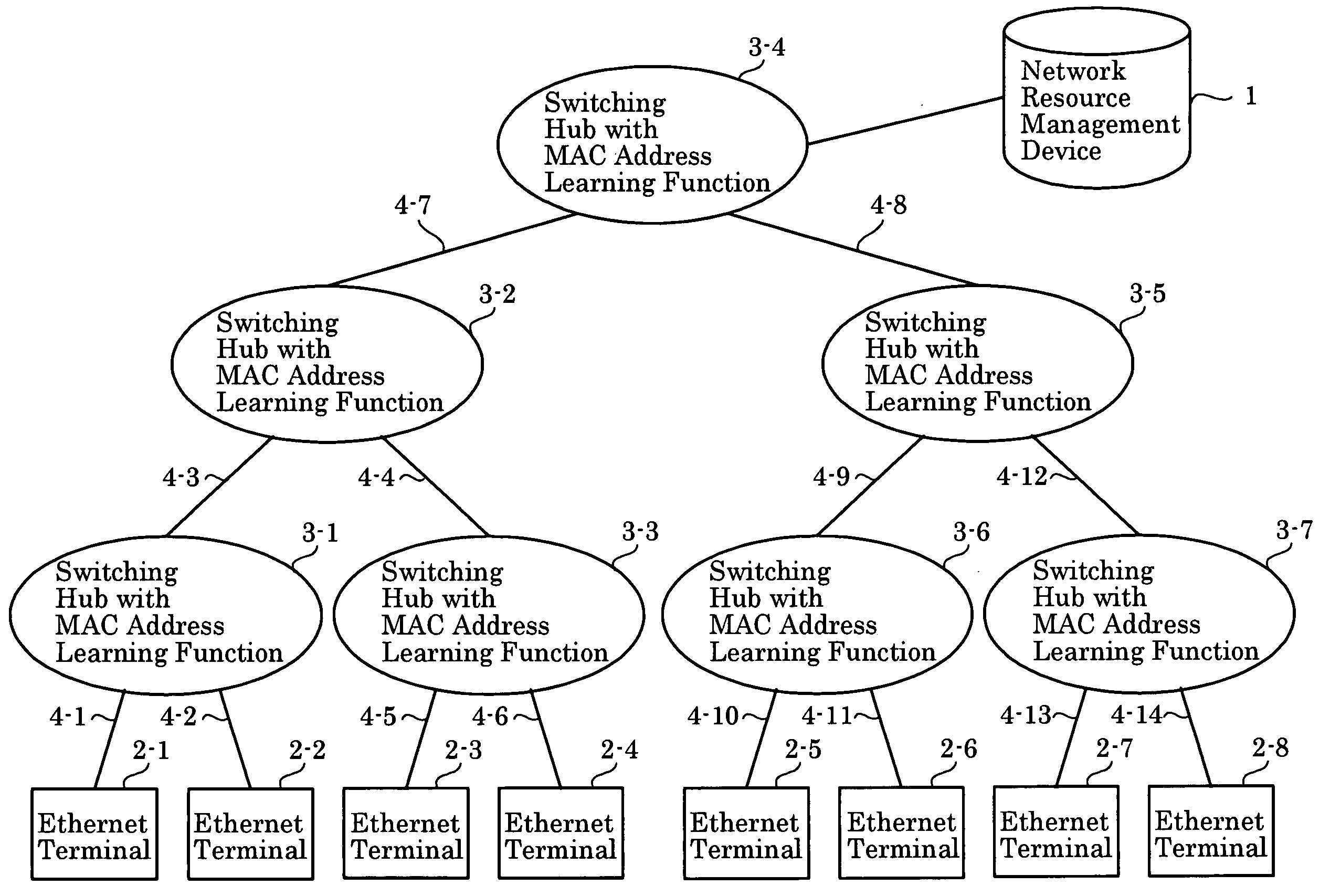
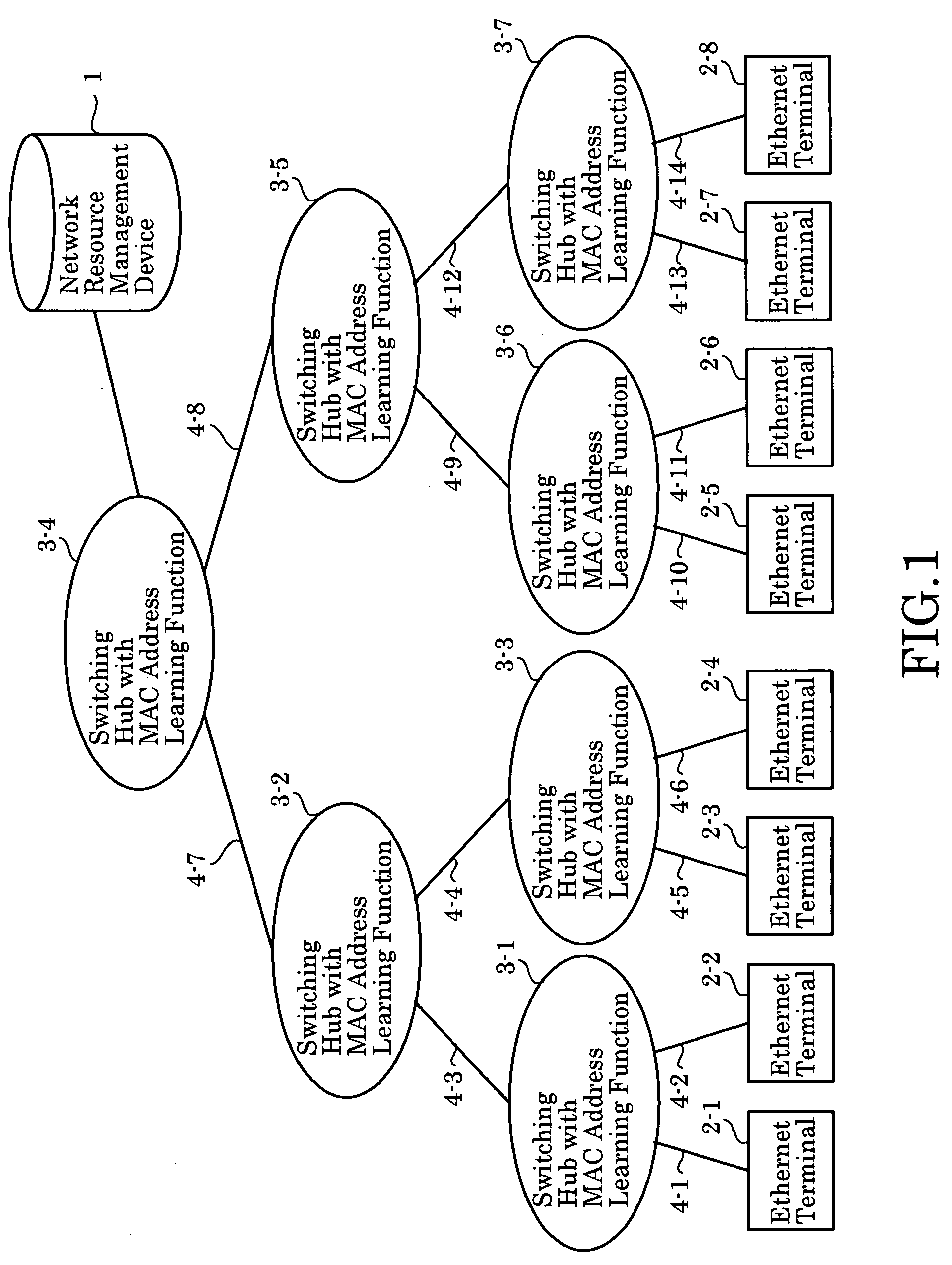
[0106]FIG. 1 is a block diagram illustrating an embodiment of the present invention. This network is composed of network resource management device 1, Ethernet terminals (hereinafter referred to simply as “terminals”) 2-1 to 2-8, switching hubs equipped with MAC address learning function 3-1 to 3-7, and Ethernet transmission links (hereinafter referred to simply as “transmission links”) 4.

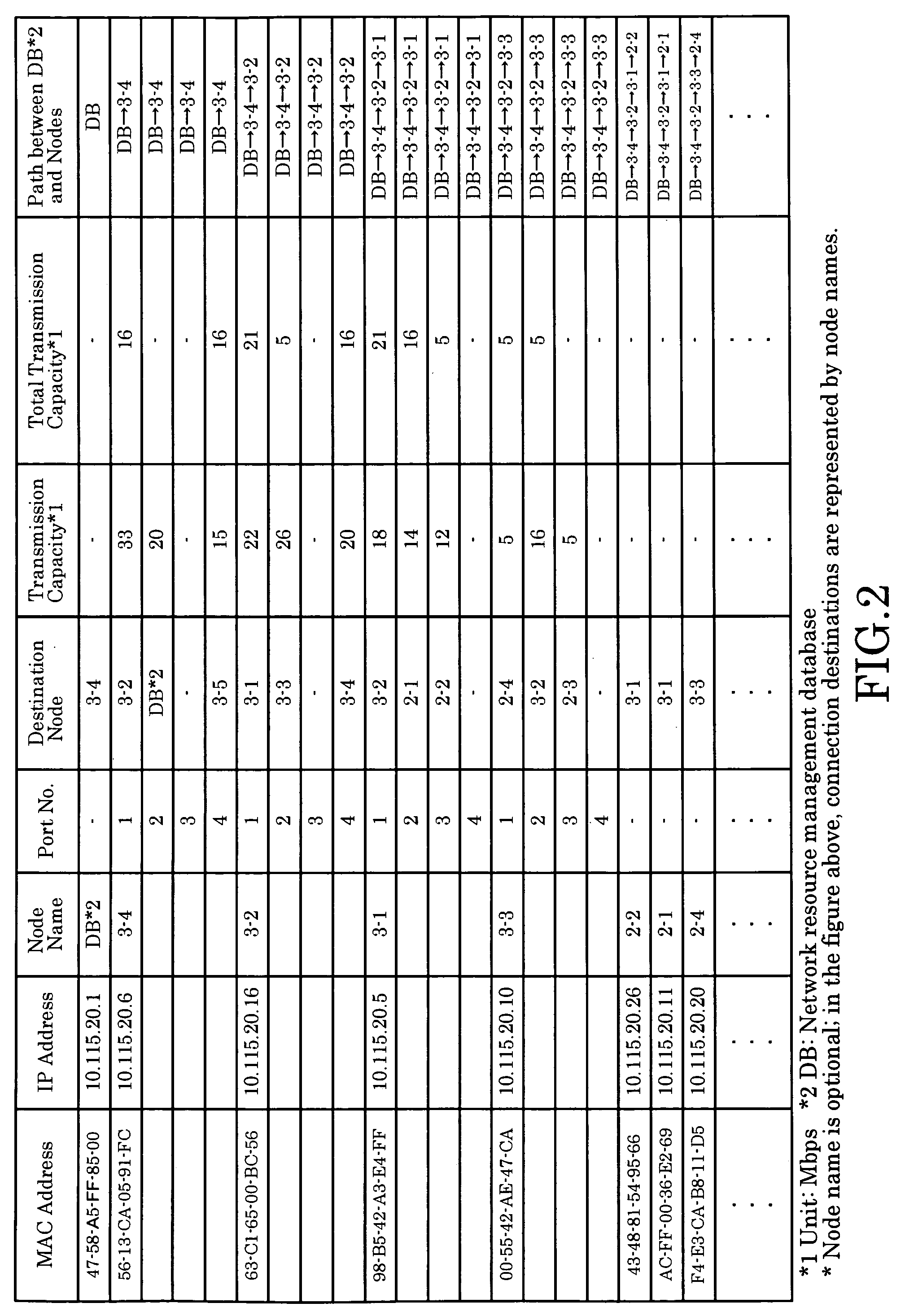
[0107]FIG. 2 is a diagram illustrating the configuration of a management database used for capacity allocation to network transmission links (network topology and transmission link capacity allocation). FIG. 3 is a diagram illustrating the configuration of a communication connection management database. The network resource management device has a database for management of capacity allocation to network transmission links, which is illustrated in FIG. 2 and is based on transmission capacity and network topology used for management, and a communication connection management database, which is illus...

embodiment 2

[0125]Operation implementing bidirectional communication using a communication sequence leading to the establishment of communication, which is shown in the first embodiment, is explained by referring to FIG. 2, FIG. 3, and FIG. 9.

[0126]FIG. 9 is a sequence diagram used to explain the communication procedure of the second embodiment. As illustrated in FIG. 9, when terminal 2-1 establishes bidirectional stream data communication with terminal 2-8, the network management device receives a Call Request (CR) packet from call request terminal 2-1 and learns the MAC address of terminal 2-1 (hereinafter referred to as the request source MAC address), the IP address of terminal 2-1 (hereinafter referred to as the request source IP address), the IP address of terminal 2-8 (hereinafter referred to as the request destination IP address), and the reserved transmission capacity that terminal 2-1 intends to use. Based on this information, the network resource management device allocates transmiss...

embodiment 3

[0131]FIG. 2, FIG. 3, and FIG. 10 are used to explain that once the stream data transfer described in the first embodiment is established, the already assured transmission capacity can be modified thereafter.

[0132]Upon establishing the end-to-end communication, the network resource management device receives a Call Request (CR) packet specifying the transmission capacity to be modified and the request destination IP address from the call request terminal that modifies the transmission capacity. Subsequently, the network resource management device records the transmission capacity to be modified in the reserved transmission capacity field of the communication connection management database illustrated in FIG. 3, and assures the transmission capacity recorded under “reserved transmission capacity” by the database for management of capacity allocation to network transmission links illustrated in FIG. 2.

[0133]Subsequently, the network resource management device uses a Call Accept (CA) p...


PUM


Abstract

The invention implements inter-terminal transmission with guaranteed capacity based on the single-path configuration function of networks composed of switching hubs with an MAC address learning function and centralized management of transmission capacity, without control over hubs. The capacity to be used by transmission links on a network is stored in advance and transmission capacity along the path to be used is allocated based on requests from terminals, with the allocation removed using a Terminate Request. At such time, by using transmission links and switching hubs with an MAC address learning function, transmission is limited to single-path transmission.

Description

TECHNICAL FIELD[0001]The present invention relates to network resource management used to provide real-time services, for which QoS (Quality of Service) is required, such as video communication, voice conversations, streaming, etc. In particular, the present invention relates to allocation of transmission capacity for communication, and to management thereof, performed by deciding the values of the maximum frame (packet) rate and the maximum transmission delay time on Ethernet (registered trademark) networks.BACKGROUND ART[0002]The IEEE 802.1Q / p standard for VLANs (Virtual LANs) is used to provide services requiring QoS on Ethernet networks. According to this standard, frames are provided with priority control tags, with each frame classified into eight types of priority: highest-priority Network Management, Voice, Video, Controlled-Load, Excellent Effort, Best Effort, Spare, and lowest-priority Background. The priority is used to perform transmission with priority processing in net...

Claims


Application Information

Patent Timeline
IPC IPC(8): G08C15/00H04L12/54
CPCH04L12/5695H04L47/72H04L47/781H04L47/70
Inventor TOKURA, NOBUYUKIINOUE, KEISUKEYAGO, HARUO
Owner YAZAKI CORP
Why Eureka
Try Eureka