Solenoid valve and fuel injection valve having the same

a solenoid valve and fuel injection technology, applied in the field of solenoid valves, can solve the problems of impaired response of the valve element of the solenoid valve, and achieve the effect of quick actuation of the valve elemen

Active Publication Date: 2011-05-17
DENSO CORP
View PDF18 Cites 6 Cited by
  • Summary
  • Abstract
  • Description
  • Claims
  • Application Information

AI Technical Summary

Problems solved by technology

Consequently, response of the valve element of the solenoid valve may be impaired when the coil is de-energized.

Method used


Image

  • Solenoid valve and fuel injection valve having the same
  • Solenoid valve and fuel injection valve having the same
  • Solenoid valve and fuel injection valve having the same

Examples


first embodiment

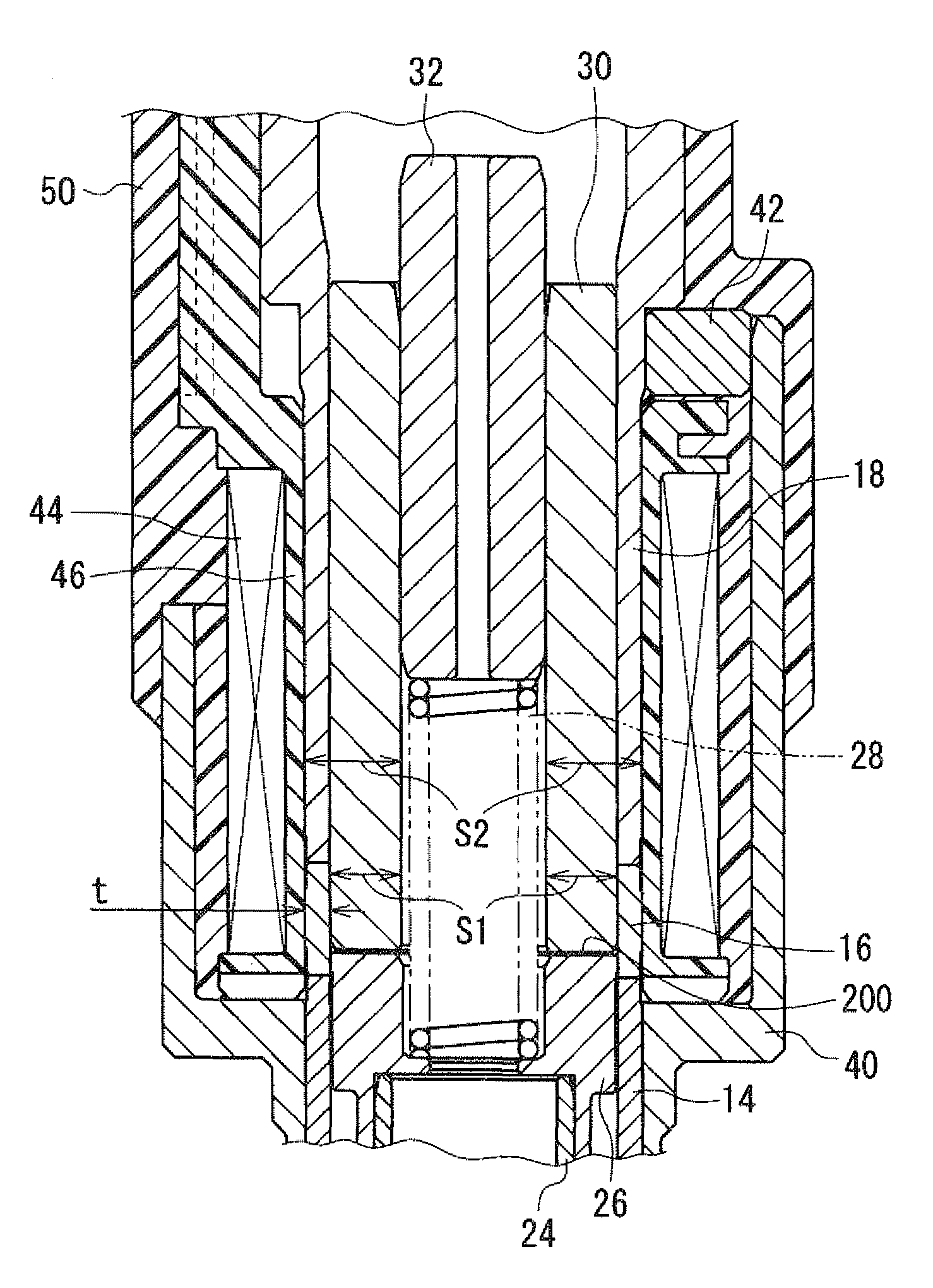
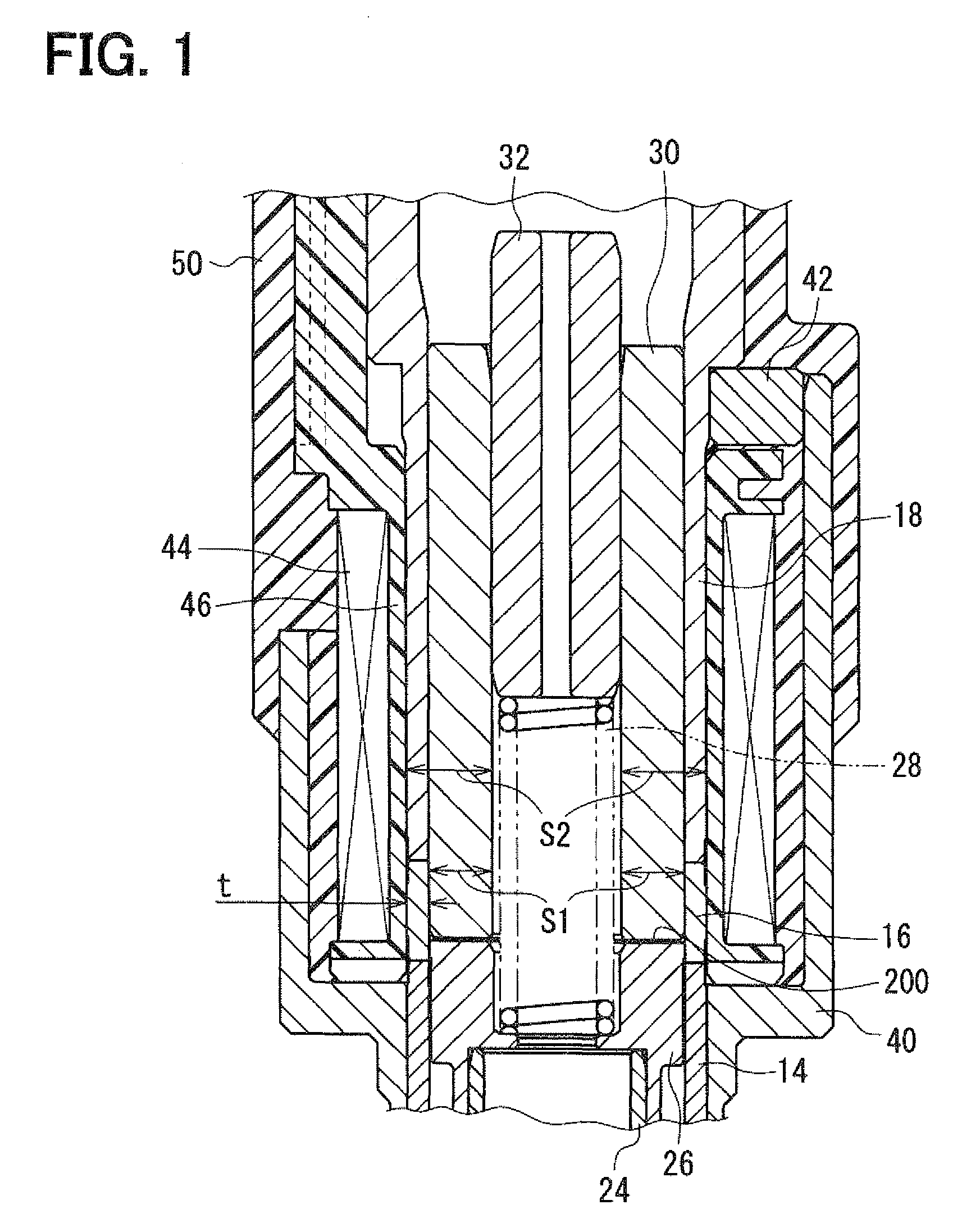
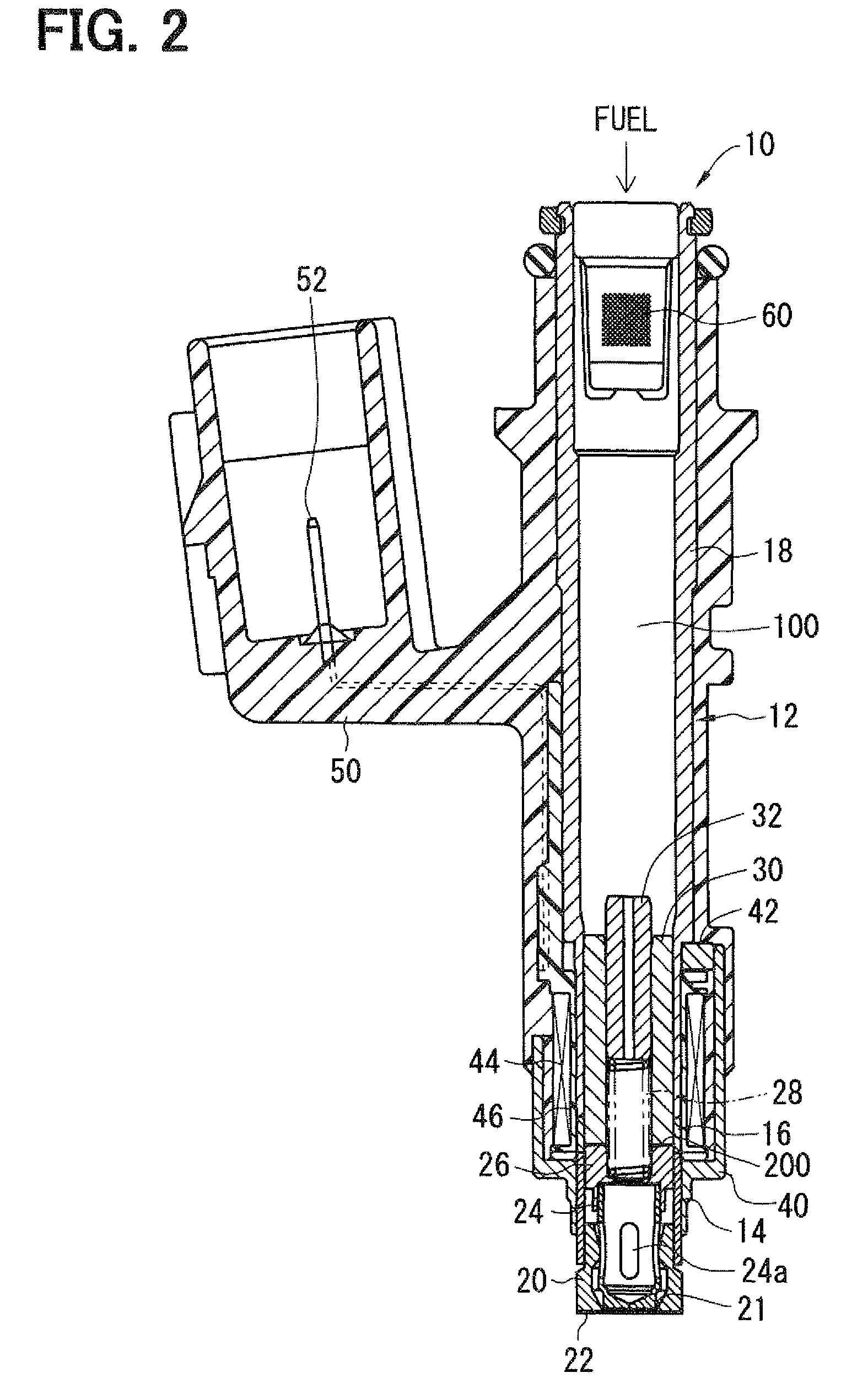
[0019]As shown in FIGS. 1, 2, a fuel injection valve 10 is provided to, for example, a gasoline engine. A cylindrical member 12 is a substantially cylindrical member formed from a magnetic material or a nonmagnetic material. The cylindrical member 12 has a fuel passage 100, which accommodates a valve body 20, a valve element 24, a movable core 26, a spring 28, a stationary core 30, and the like.

[0020]Referring to FIG. 2, the cylindrical member 12 has a first magnetic cylindrical member 14, a nonmagnetic cylindrical member 16, and a second magnetic cylindrical member 18, which are arranged in this order from the valve body 20 located on the lower side thereof. The first magnetic cylindrical member 14, the nonmagnetic cylindrical member 16, and the second magnetic cylindrical member 18 are integrally joined with each other by, for example, laser welding. The first magnetic cylindrical member 14, the nonmagnetic cylindrical member 16, and the second magnetic cylindrical member 18 respe...

fourth embodiments

Second to Fourth Embodiments

[0037]As shown in FIG. 6, according to the second embodiment, the outer circumferential periphery of a nonmagnetic cylindrical member 70 has a recess 72. The recess 72 is substantially in an annular shape and axially extends.

[0038]As shown in FIG. 7, according to the third embodiment, the outer circumferential periphery of a nonmagnetic cylindrical member 80 has multiple recesses 82 each being substantially in an annular shape. The outer circumferential periphery of the nonmagnetic cylindrical member 80 is in a wave shape in cross section. That is, the nonmagnetic cylindrical member 80 has a substantially corrugated outer periphery.

[0039]According to the second and third embodiments, the nonmagnetic cylindrical member 70, 80 having the recess 72, 82 are reduced in volume compared with the nonmagnetic cylindrical member 16 in the first embodiment. In the present structure, an eddy current caused in the nonmagnetic cylindrical member 70, 80 in response to t...


PUM


Abstract

A solenoid valve includes a movable core, a magnetic opposed portion opposed to the movable core, a nonmagnetic cylindrical portion, a first magnetic cylindrical portion axially close to the movable core, and a second magnetic cylindrical portion located radially outside of the magnetic opposed portion. The nonmagnetic cylindrical portion surrounds radially outside of a gap between the magnetic opposed portion and the movable core. A coil is provided radially outside of the nonmagnetic cylindrical portion. A thickness t of the nonmagnetic cylindrical portion, a cross-sectional area S1 of the magnetic opposed portion, and a total cross-sectional area S2 of both the magnetic opposed portion and the second magnetic cylindrical portion having the thickness t satisfy the relationships of t≦0.6 mm and 0.55≦(S1 / S2).

Description

CROSS REFERENCE TO RELATED APPLICATIONS[0001]This application is based on and incorporates herein by reference Japanese Patent Applications No. 2007-78478 filed on Mar. 26, 2007 and No. 2008-15037 filed on Jan. 25, 2008.FIELD OF THE INVENTION[0002]The present invention relates to a solenoid valve. The present invention further relates to a fuel injection valve having the solenoid valve.BACKGROUND OF THE INVENTION[0003]For example, U.S. Pat. No. 5,769,391 (JP-A-11-500509) discloses a fuel injection valve having a solenoid valve including a stationary core, a movable core, a valve element, and a coil. When the coil is energized, the stationary core and the movable core therebetween generate magnetic attractive force to manipulate the valve element together with the movable core so as to control communication in a fluid passage for intermitting fuel injection. In U.S. Pat. No. 5,769,391, a movable core side magnetic portion surrounds an outer circumferential periphery of the movable co...

Claims


Application Information

Patent Timeline
Patent Type & Authority Patents(United States)
IPC IPC(8): F16K31/02
CPCF02M51/0685H01F7/081F16K31/0675F02M63/0019F02M61/042F02M63/0015F02M2200/08F02M2200/9069
Inventor SUGIYAMA, KOUICHIKUROIWA, KAZUNARI
Owner DENSO CORP
Why Eureka
Try Eureka