Fuel cell system with fluid stream recirculation

a fuel cell and fluid stream technology, applied in the field of fuel cell systems, can solve the problems of insufficient design of jet ejectors, insufficient fuel cell stack inlet flow rate, and insufficient nozzle and/or throat portion of diffusers,

Inactive Publication Date: 2005-03-24
FORD MOTOR CO +1
View PDF15 Cites 72 Cited by
  • Summary
  • Abstract
  • Description
  • Claims
  • Application Information

AI Technical Summary

Benefits of technology

[0020] a high-flow diffuser fluidly connected to the discharge outlet.

Problems solved by technology

In light of the wide spectrum of fuel cell stack hydrogen inlet stream flow rates over which the jet ejector must operate, it has proven difficult to design a satisfactory jet ejector.
Designing a jet ejector to supply the needed inlet flow rate to the fuel cell stack during maximum-load demand periods results in the nozzle and / or the throat portion of the diffuser being too large to recirculate the needed hydrogen during low-load demand periods (e.g., idle periods).
Conversely, designing a jet ejector to recirculate the needed hydrogen during low-load demand periods results in the nozzle and / or the throat portion of the diffuser being too small to supply the needed inlet flow rate to the fuel cell stack during maximum-load demand periods.
However, having two separate ejectors and the related fluid circuitry leads to space requirement concerns in typical automotive applications.
Furthermore, the transition point in such systems, more specifically when the motive flow course is changed from the low-flow to the high-flow ejector, typically experiences a sudden drop in recirculation that often falls below the needed minimum entrainement level.

Method used


Image

  • Fuel cell system with fluid stream recirculation
  • Fuel cell system with fluid stream recirculation
  • Fuel cell system with fluid stream recirculation

Examples


Embodiment Construction

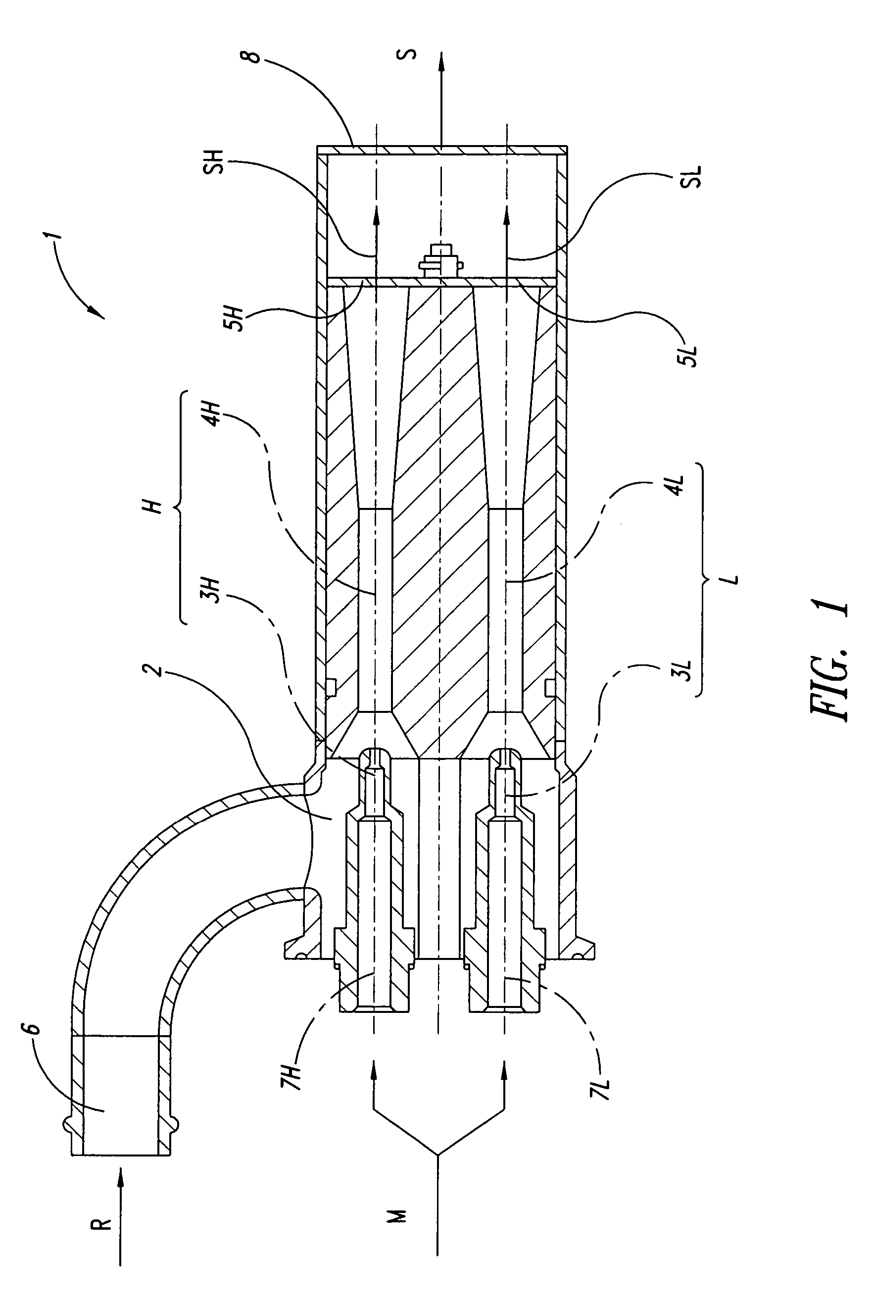
[0091]FIG. 1 shows a double jet ejector 1 according to an embodiment of the invention. Jet ejector 1 includes a common suction chamber 2, a low-flow nozzle 3L and a low-flow diffuser 4L (which, for the sake of simplicity, will collectively be referred to below as low-flow ejector L), a low-flow check valve 5L, a high-flow nozzle 3H and a high-flow diffuser 4H (which, for the sake of simplicity, will collectively be referred to below as high-flow ejector H), a high-flow check valve 5H, a suction inlet 6, fluidly connected to common suction chamber 2, a low-flow motive inlet 7L, fluidly connected to low-flow nozzle 3L, a high-flow motive inlet 7H, fluidly connected to high-flow nozzle 3H, and a discharge outlet 8, fluidly connected to low-flow and high-flow diffusers 4L and 4H. Suction inlet 6 is configured to receive a recirculated flow R from a fuel cell stack's exhaust stream outlet, low-flow motive inlet 7L and high-flow motive inlet 7H are configured to receive a motive flow M fr...


PUM

PropertyMeasurementUnit
steady-state pressureaaaaaaaaaa
pressureaaaaaaaaaa

Abstract

An electric power generation system has a multiple jet ejector assembly for recirculating an exhaust stream. The system includes a fuel cell stack having a reactant stream inlet, a reactant stream outlet and at least one fuel cell. A pressurized reactant supply provides a reactant to the multiple jet ejector assembly. The multiple jet ejector assembly includes two motive flow inlets, one suction inlet, fluidly connected to the reactant stream outlet to receive a recirculated flow from the fuel cell stack, and one discharge outlet, fluidly connected to the reactant stream inlet to provide an inlet stream to the fuel cell stack. A pressure regulator is interposed between the pressurized reactant supply and the two motive flow inlets of the multiple jet ejector assembly. A first solenoid valve is interposed between the first motive flow inlet and the regulator. A second solenoid valve is interposed between the second motive flow inlet and the regulator. A by-pass line connects the pressurized reactant supply to the second motive flow inlet. A by-pass solenoid valve is interposed in the bypass line between the pressurized reactant supply and the second motive flow inlet. During low-load operating conditions, the second solenoid valve is open and the first and by-pass solenoid valves are closed, so that pressurized reactant, controlled by the regulator, is directed to the second motive flow inlet. During high-load operating conditions, the second solenoid valve is closed and the first and by-pass solenoid valves are open, so that pressurized reactant, controlled by the regulator, is directed to the first motive flow inlet and pressurized reactant, not controlled by the regulator, is directed to the second motive flow inlet.

Description

BACKGROUND OF THE INVENTION [0001] 1. Field of the Invention [0002] The present invention generally relates to fuel cell systems and, more particularly, to fuel cell systems with recirculation of a fluid stream. [0003] 2. Description of the Related Art [0004] Electrochemical fuel cell assemblies convert reactants, namely fuel and oxidant, to generate electric power and reaction products. Electrochemical fuel cell assemblies generally employ an electrolyte disposed between two electrodes, namely a cathode and an anode. The electrodes generally each comprise a porous, electrically conductive sheet material and an electrocatalyst disposed at the interface between the electrolyte and the electrode layers to induce the desired electrochemical reactions. The location of the electrocatalyst generally defines the electrochemically active area. [0005] Solid polymer fuel cell assemblies typically employ a membrane electrode assembly (“MEA”) consisting of a solid polymer electrolyte, or ion ex...

Claims


Application Information

Patent Timeline
Patent Type & Authority Applications(United States)
IPC IPC(8): F04F5/46H01M8/04
CPCF04F5/466H01M8/04097Y02T90/32H01M2250/20Y02E60/50H01M8/04104Y02T90/40H01M8/04
Inventor BLASZCZYK, JANUSZSCHMIDT, RAINERFLECK, WOLFRAMPATERSON, PAUL L.
Owner FORD MOTOR CO
Why Eureka
Try Eureka