Bipolar valve having permanent magnet

a bipolar valve and permanent magnet technology, applied in the direction of valve operating means/release devices, combustion air/fuel air treatment, machines/engines, etc., can solve the problems of increasing manufacturing and other costs, increasing the amount of components needed,

Active Publication Date: 2006-03-14
SIEMENS VDO AUTOMOTIVE CORP
View PDF6 Cites 75 Cited by
  • Summary
  • Abstract
  • Description
  • Claims
  • Application Information

AI Technical Summary

Benefits of technology

[0006]The invention is directed to a solenoid for use in valves used in evaporative emission control systems, such as canister purge valves or vent solenoid valves. The solenoid includes a housing having an inlet port and an outlet port. The housing further includes a guide element having a bobbin section. A valve shaft is slidably mounted to the guide element, wherein the valve shaft includes a permanent magnet and a valve element. The valve element is movable between a closed position wherein the inlet port is closed and an open position wherein the inlet port is opened. A coil is formed on the bobbin adjacent the magnet. In use, the coil generates a first directional magnetic field that is oriented to cause the magnet to be repelled to thus move the valve element to the open position. The coil also generates a second directional magnetic field that is oriented to cause a magnetic attraction with the magnet to move the valve element to the closed position.

Problems solved by technology

However, the use of such valves increases the amount of components needed and thus increases manufacturing and other costs.

Method used


Image

  • Bipolar valve having permanent magnet
  • Bipolar valve having permanent magnet
  • Bipolar valve having permanent magnet

Examples


Embodiment Construction

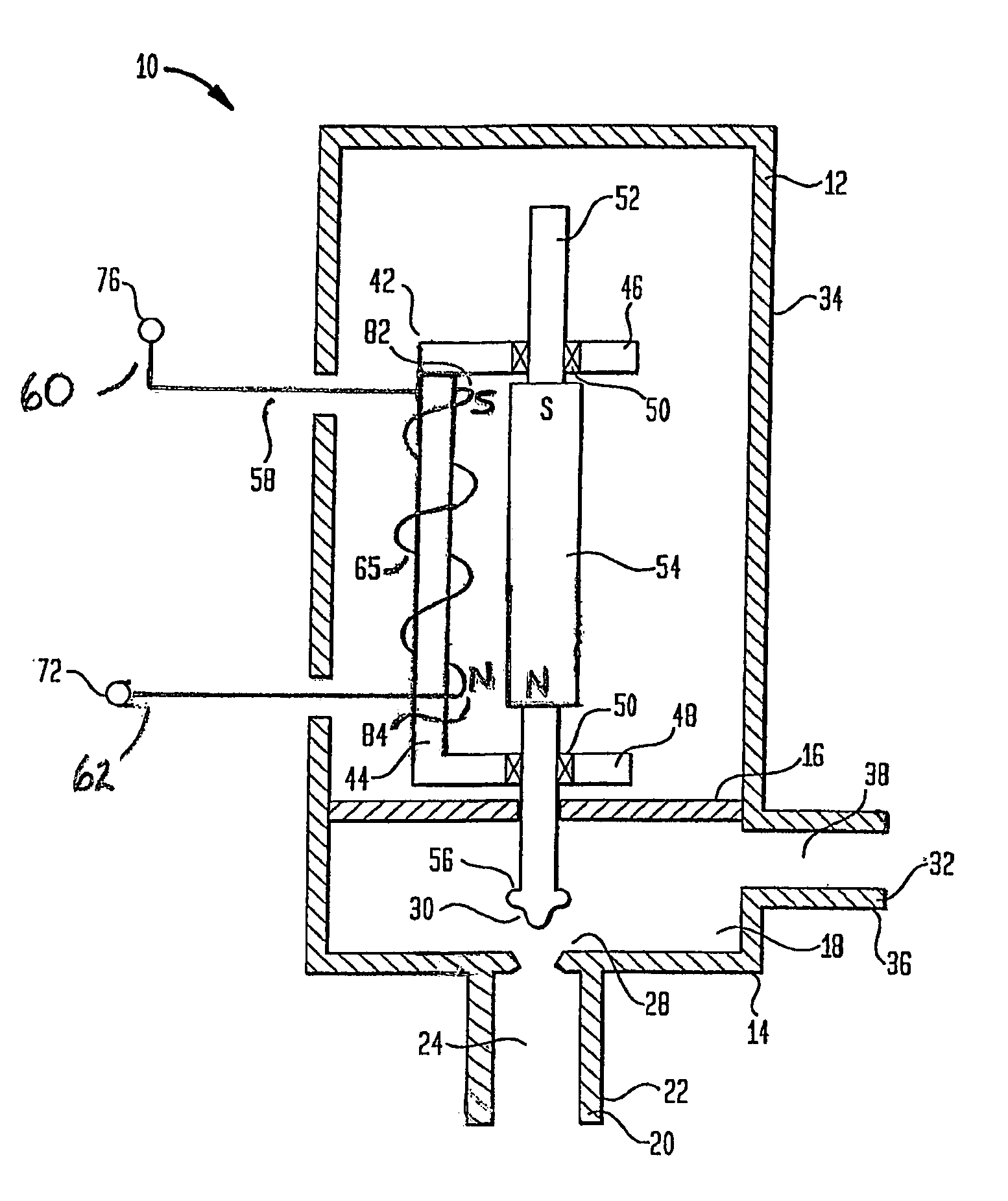
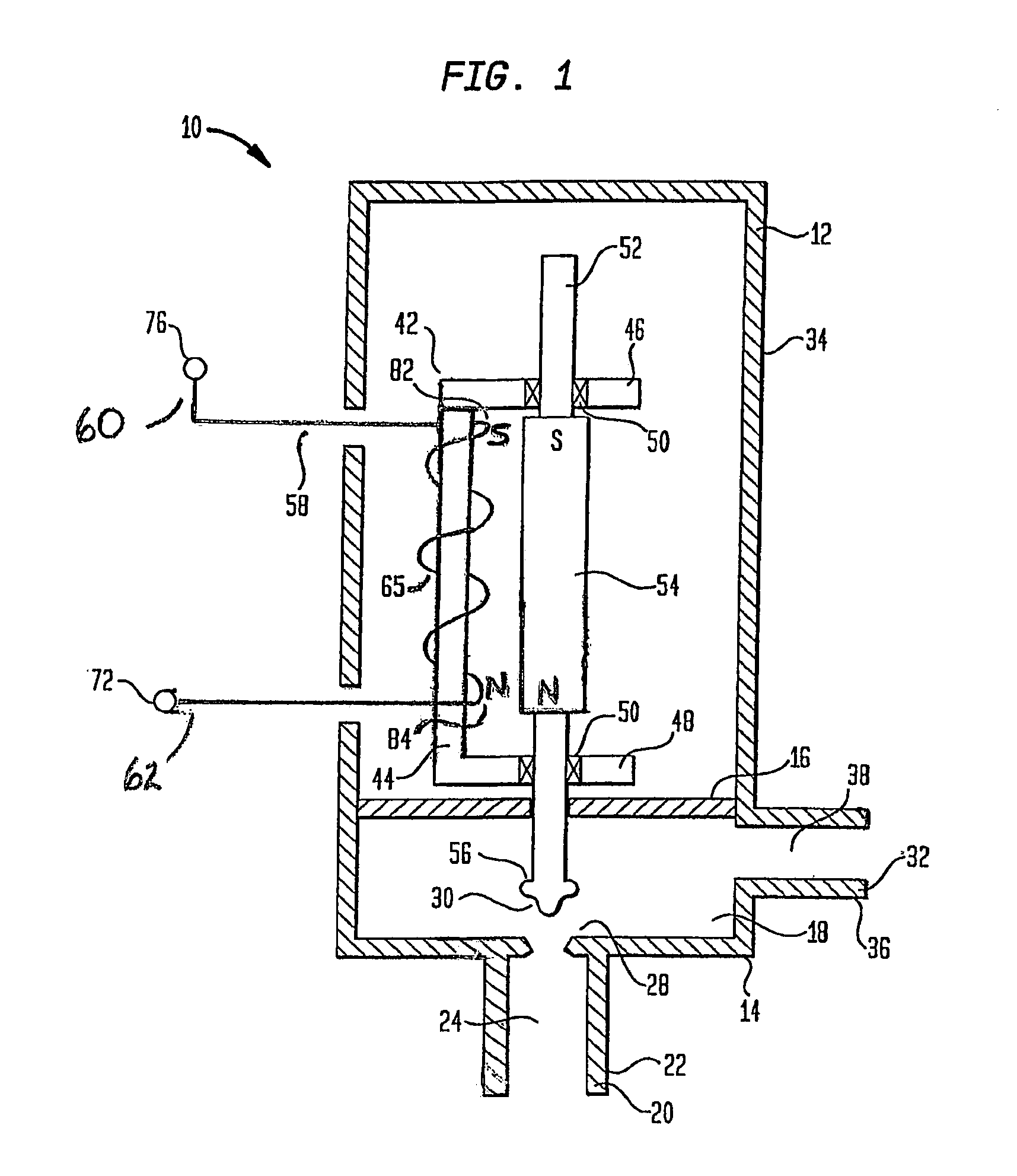
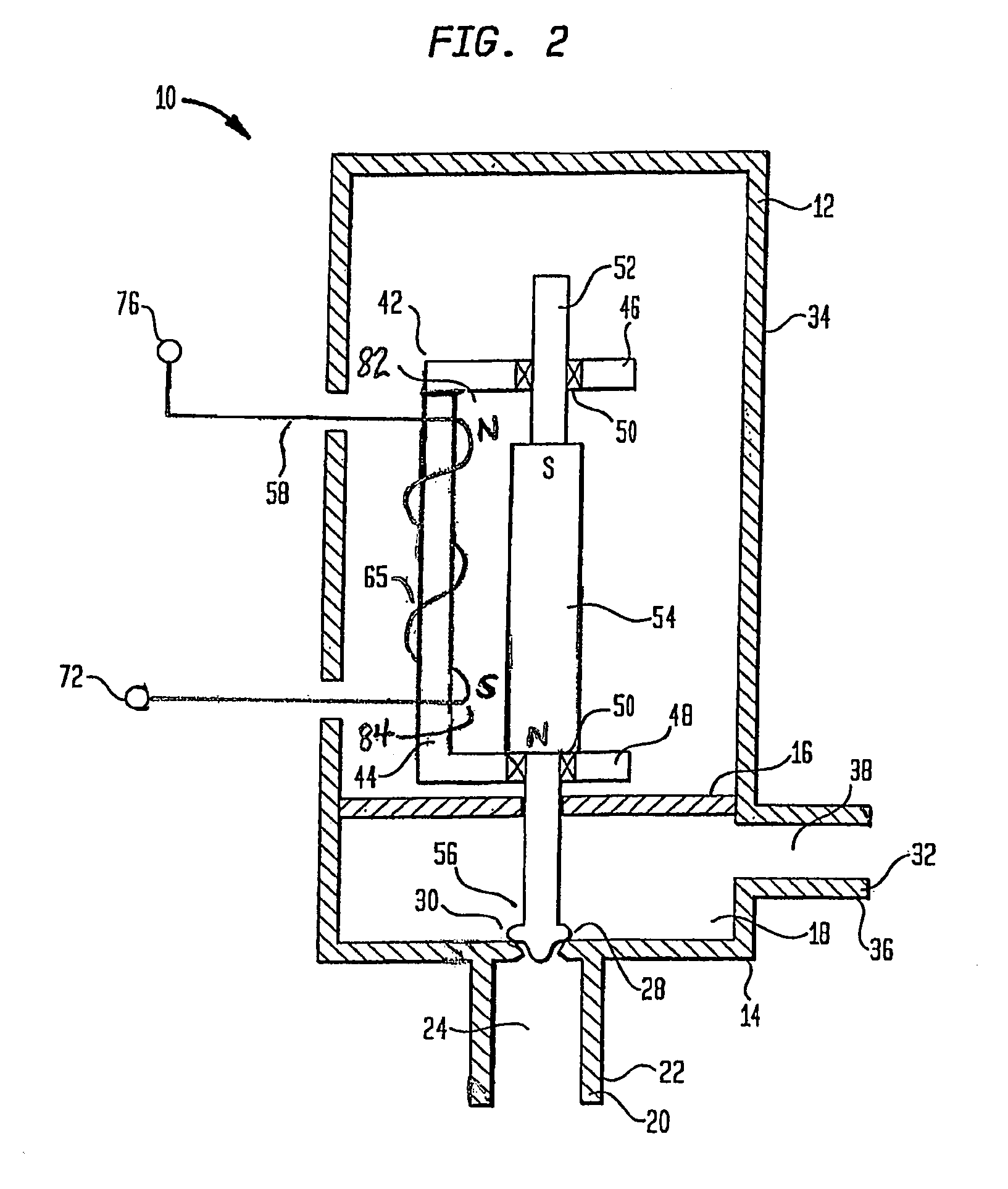
[0011]While this invention is susceptible of embodiment in many different forms, there is shown in the drawings and will herein be described in detail specific embodiments, with the understanding that the present disclosure is to be considered as an example of the principles of the invention and not intended to limit the invention to the specific embodiments shown and described. In the description below, like reference numerals are used to describe the same, similar or corresponding parts in the several views of FIGS. 1–3.

[0012]The principles of the present invention may be applied to either canister purge valves or vent solenoid valves. For purposes of clarity, the invention will be described in relation to a canister purge valve configuration although it is understood that the principles of the present invention are also applicable to vent solenoid valves. Referring to FIG. 1, a cross sectional view of a bipolar canister purge valve 10 in accordance with the present invention is s...


PUM


Abstract

A solenoid for use in valves used in evaporative emission control systems, such as canister purge valves or vent solenoid valves. The solenoid includes a housing having an inlet port and an outlet port. The housing further includes a guide element having a bobbin section. A valve shaft is slidably mounted to the guide element, wherein the valve shaft includes a permanent magnet and a valve element. The valve element is movable between a closed position wherein the inlet port is closed and an open position wherein the inlet port is opened. A coil is formed on the bobbin adjacent the magnet. In use, the coil generates directional magnetic fields oriented to cause the magnet to be repelled to move the valve element to the open position and oriented to cause a magnetic attraction with the magnet to move the valve element to the closed position.

Description

FIELD OF THE INVENTION[0001]This invention relates to evaporative emission control systems for internal combustion engines, and more particularly, to a valve having a bipolar coil for generating magnetic fields which interact with a permanent magnet to selectively open and close a valve element.BACKGROUND OF THE INVENTION[0002]Motor vehicles having an internal combustion engine typically include an evaporative emission control system which serves to reduce fuel vapor emissions. Such systems include a vapor collection canister having carbon or other material which serves to absorb fuel vapors that are generated within a motor vehicle fuel system. A canister purge valve is located between the canister and an engine intake manifold. The canister purge valve may be opened or closed to either place the canister in fluid communication with the engine intake manifold or to isolate the canister from the engine intake manifold, respectively. The canister is also connected to a vent solenoid ...

Claims


Application Information

Patent Timeline
Patent Type & Authority Patents(United States)
IPC IPC(8): F16K31/02
CPCF02M25/0836F16K31/082F16K24/04F02M25/0809F02M2025/0845
Inventor WELDON, CRAIG ANDREWEVERINGHAM, GARY
Owner SIEMENS VDO AUTOMOTIVE CORP
Why Eureka
Try Eureka