
Magnetically preloaded anti-rotation guide for a transducer

a technology of anti-rotation guide and transducer, which is applied in the direction of speed-changing/reversing arrangement, maintaining head carrier alignment, instruments, etc., can solve the problems of poor actuator performance, reliability and performance problems of spring preloading mechanism, and may be a source of reliability and performance issues

Active Publication Date: 2011-05-17
ORACLE INT CORP
View PDF6 Cites 5 Cited by
  • Summary
  • Abstract
  • Description
  • Claims
  • Application Information

AI Technical Summary

Problems solved by technology

Spring preloading mechanisms may be a source of reliability and performance issues.
Reliability and performance problems may arise due to component fatigue, component wear, and unpredictable frictional forces that may occur at preload component interfaces.
Such reliability and performance problems may contribute to poor actuator performance and reduced anti-rotation guide and head actuator product life.
Anti-rotation guide spring preload mechanisms are small parts of considerable complexity.
The cost of assembling such small, complex parts increases the cost of assembling the anti-rotation guides and head actuator assemblies.

Method used


Image

  • Magnetically preloaded anti-rotation guide for a transducer
  • Magnetically preloaded anti-rotation guide for a transducer
  • Magnetically preloaded anti-rotation guide for a transducer

Examples


Embodiment Construction

)

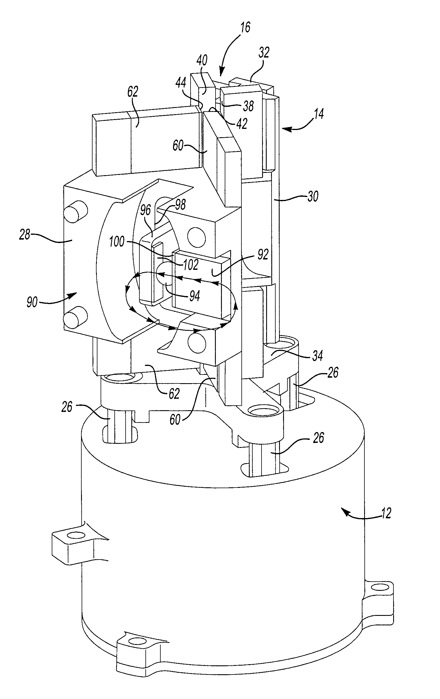
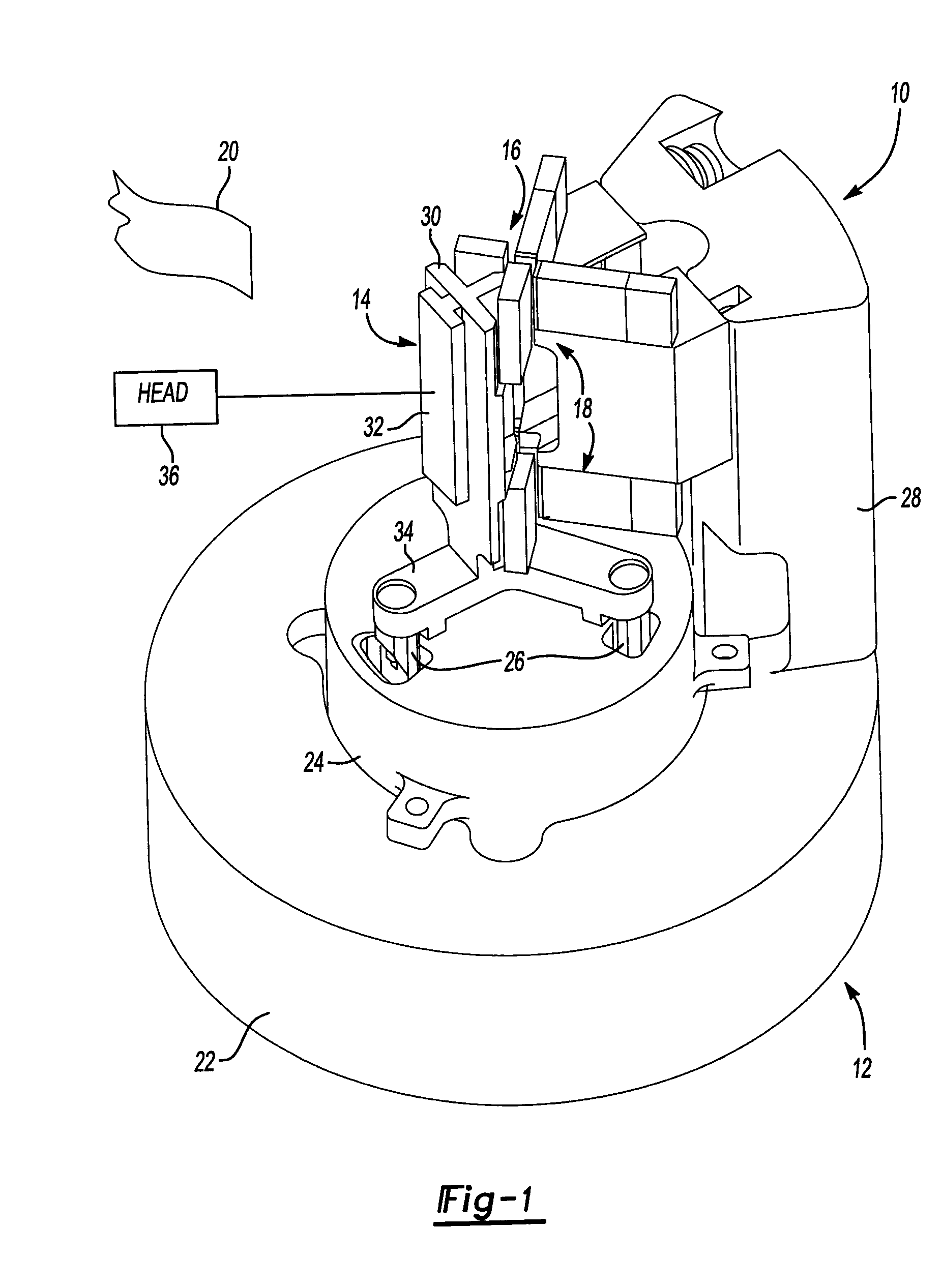
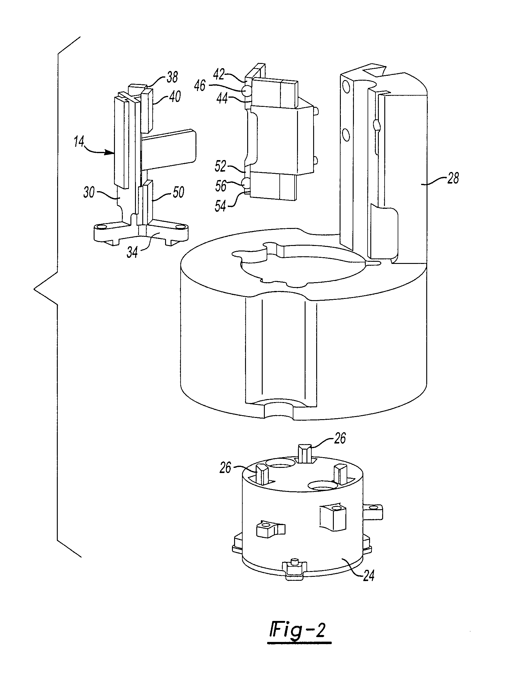
[0025]Referring to FIG. 1, a transducer head positioning apparatus 10 is illustrated. The transducer head positioning apparatus 10 includes a base assembly 12 and a head assembly 14. The head assembly 14 is supported in part by a linear motion track 16 that is defined by both the base assembly 12 and the head assembly 14. A magnetic coupling system is generally represented by reference numeral 18 that functions in conjunction with the linear motion track 16 to guide the movement of the head assembly 14 relative to the base assembly 12. The head assembly 14 is used to read and write data to a data storage tape 20 in the illustrated embodiment. However, it should be understood that the invention is not limited to tape storage applications and could be adapted, for example, to disk storage applications.

[0026]The base assembly 12 includes a base 22 and a linear motor 24. The linear motor 24 has a plurality of legs 26 that operatively engage the head assembly 14 to move the head assembl...


PUM

PropertyMeasurementUnit
movementaaaaaaaaaa
anti-rotationaaaaaaaaaa
frictional forcesaaaaaaaaaa

Abstract

A transducer positioning apparatus is provided that supports a read / write head on a data storage machine and biases the head against rotation. The transducer positioning apparatus may comprise a base that includes a linear drive motor and a support frame to which the read / write head is secured. The support frame is reciprocally driven by the linear drive motor relative to the base. A magnetic coupling is provided between the base and the support frame that resists movement of the frame other than the reciprocal movement of the support frame relative to the base. A method is also disclosed for magnetically biasing a movable head of a transducer against rotation.

Description

BACKGROUND OF THE INVENTION[0001]1. Field of the Invention[0002]The invention relates to an anti-rotation guide for a media drive transducer.[0003]2. Background Art[0004]Anti-rotation guides for transducers are used in media drives to inhibit rotational movement of a transducer when the direction of tape movement is reversed with respect to a tape head. Examples of transducer positioning devices are disclosed in U.S. Pat. Nos. 6,437,946 and 6,985,430.[0005]Anti-rotation guides for transducers are generally preloaded to remove play and minimize undesirable head movements. The most common method of preloading is to use springs that bias the anti-rotation guides. Spring preloading mechanisms may be a source of reliability and performance issues. Reliability and performance problems may arise due to component fatigue, component wear, and unpredictable frictional forces that may occur at preload component interfaces. Such reliability and performance problems may contribute to poor actuat...

Claims


Application Information

Patent Timeline
Patent Type & Authority Patents(United States)
IPC IPC(8): G11B15/44
CPCG11B5/5928G11B5/584
Inventor YEAKLEY, DARRYL W.GOODKNIGHT, FRANK A.
Owner ORACLE INT CORP
Learn More