Mass flowmeter

a mass flowmeter and mass flow rate technology, applied in the field of mass flowmeters, can solve the problems of not being able to increase the nominal width simply, and achieve the effect of high mass flow rate and little energy

Active Publication Date: 2011-05-24
KRONE GMBH
View PDF11 Cites 6 Cited by
  • Summary
  • Abstract
  • Description
  • Claims
  • Application Information

AI Technical Summary

Benefits of technology

[0007]According to the invention, the stated object is achieved, first of all, and essentially in the case of the mass flowmeter under discussion in that more than two measurement tubes are provided, and in particular an even number of measurement tubes are provided. According to the invention, it has been found that an increase in the flow cross section and thus a Coriolis meter configuration which is suitable for higher mass flows can be achieved not only by increasing the nominal widths of the measurement tubes of the single-tube or two-tube mass flowmeters but also by providing further measurement tubes. The further measurement tubes advantageously make it possible to keep the oscillation behavior of the individual measurement tubes constant, and the measurement tubes can still be excited by oscillation generators which were previously suitable only for relatively small mass flowmeters, that is to say which could cope with only a relatively low mass flow rate. This means that it is also possible to produce mass flowmeters which are physically small in comparison to known single-tube or two-tube mass flowmeters, since the increase in the total flow cross section of the measurement tubes need not be compensated for by lengthening the measurement tubes since it is not essential to change the cross sections of the individual measurement tubes which are used.
[0008]It is particularly advantageous for the measurement tubes to be arranged closely—seen at right angles to the flow direction—that is to say for the flow cross section which is covered by the measurement tubes to be provided in as small an area as possible. According to the invention, when using standard measurement tubes, that is to say measurement tubes with a circular cross section, mass flowmeters allow the best possible utilization of space, and in any case utilize space considerably better than those mass flowmeters which use only a single measurement tube or two measurement tubes.
[0009]In one particularly preferred refinement of the mass flowmeter according to the invention, the measurement tubes are associated with measurement tube groups, with the measurement tubes in one measurement tube group being mechanically coupled to one another. This mechanical coupling does not refer to the couplings between the measurement tubes on the inlet and outlet sides, which necessarily result in the measurement tubes diverging or being joined together in connecting pieces on the inlet and outlet sides, with the connecting pieces being used with flanges which can connect the measurement tubes overall to a pipeline system. In fact, this refers to mechanical couplings which are provided within the oscillation area of the measurement tubes. The mechanical couplings between the measurement tubes of a measurement tube group result in the measurement tubes also being functionally associated with one another, and in simplification of the oscillation behavior of the measurement tube arrangement.
[0011]In another preferred refinement of the invention, the measurement tubes in a measurement tube group are connected to one another essentially over their entire extent—seen in the flow direction—and in particular are soldered or welded to one another. This mechanical coupling means that the measurement tubes in a measurement tube group are linked to one another without any remaining degrees of freedom for individual movement. Nevertheless, an arrangement such as this can be used to provide a mass flowmeter form which operates on the Coriolis principle and is more compact overall than is possible with single-tube or two-tube mass flowmeters.
[0012]Further preferred refinements of the invention are distinguished in that the measurement tubes or measurement tube groups are associated with one another in pairs, and each pair is equipped with separate oscillation generators and / or with separate oscillation sensors. This makes it possible to excite and to evaluate two different pairs of measurement tubes or measurement tube groups independently of one another, in particular to excite them independently of one another in different eigen forms and to evaluate the oscillations of the eigen forms separately, without the excited oscillations being mutually superimposed.

Problems solved by technology

In order to allow relatively high mass flows to be detected, it is not simply possible just to increase the nominal widths of the measurement tubes of a known mass flowmeter, since this automatically changes the oscillation behavior of the measurement tubes.

Method used


Image

  • Mass flowmeter
  • Mass flowmeter
  • Mass flowmeter

Examples


Embodiment Construction

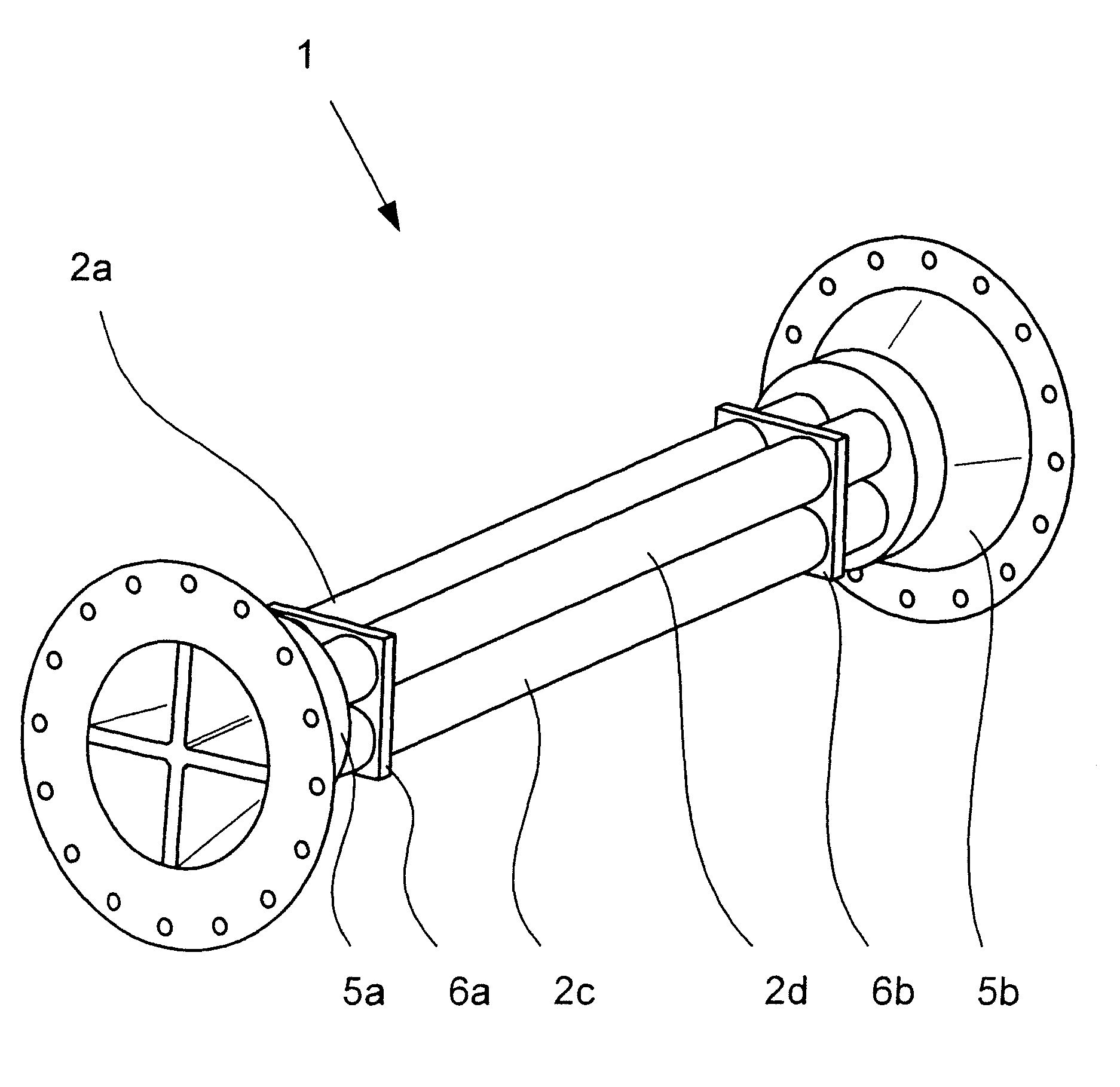
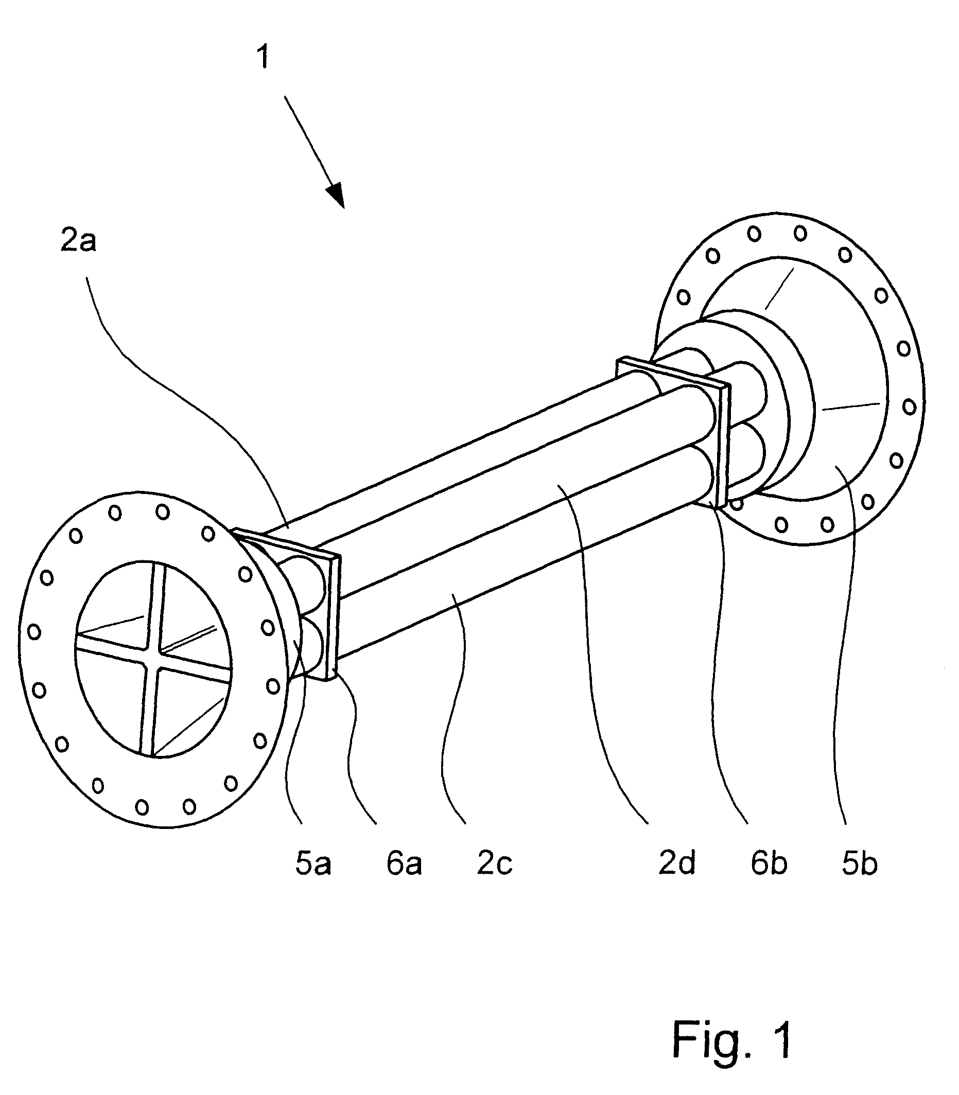
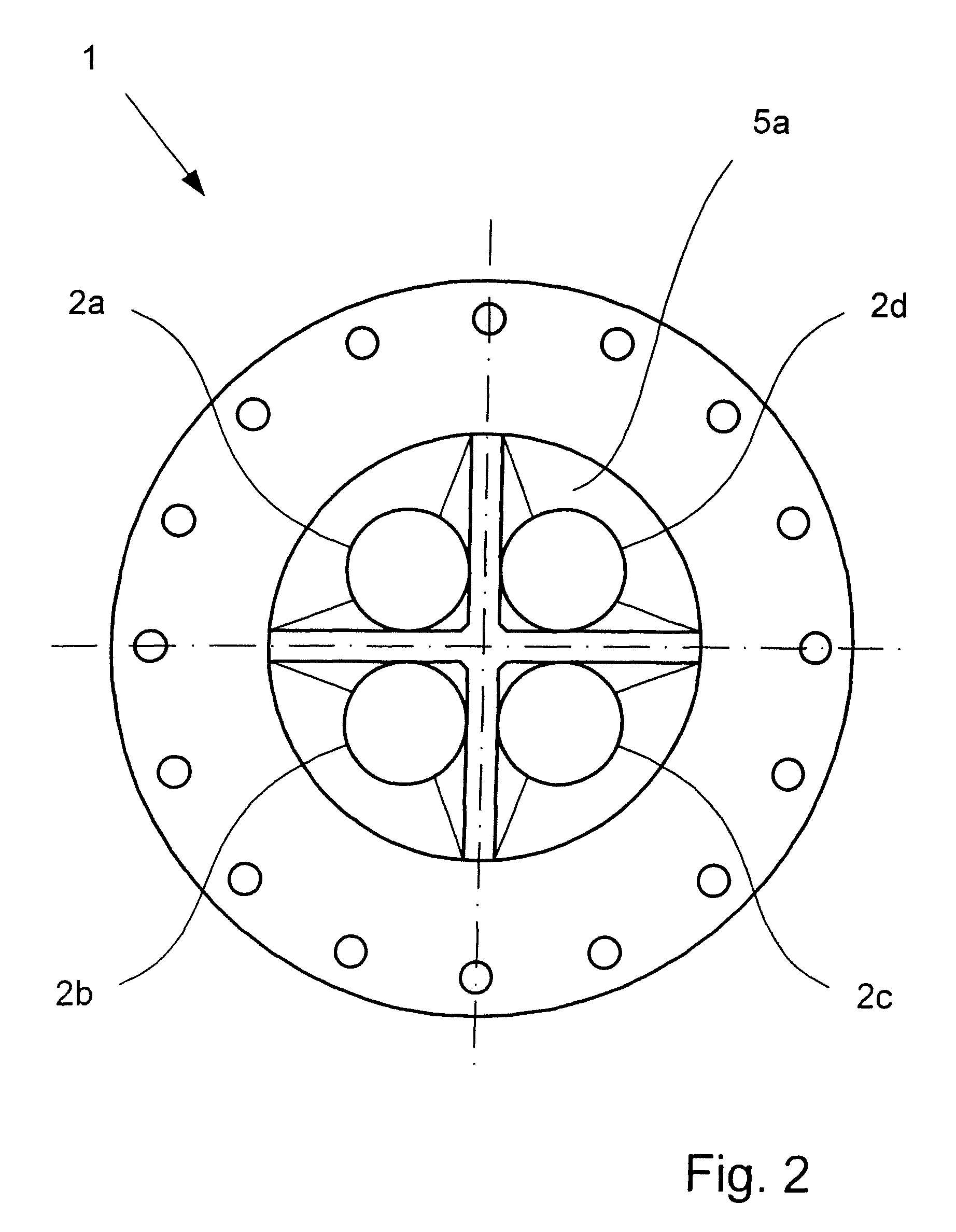
[0019]FIGS. 1 to 5 illustrate—completely or partially—mass flowmeters 1 which operate on the Coriolis principle. The figures show measurement tubes 2a, 2b, 2c, 2d through each of which a medium can flow and which can be caused to oscillate by an oscillation generator 3, in which case the excited oscillations can then be detected by oscillation sensors 4a, 4b (FIG. 3). The illustrated mass flowmeters 1 are distinguished in that not just one measurement tube 2 or two measurement tubes 2 is or are provided—as known from the prior art—but more than two measurement tubes 2 are provided, specifically a total of four measurement tubes 2a, 2b, 2c, 2d in the present case.

[0020]The plurality of measurement tubes 2a, 2b, 2c, 2d make it possible to design the mass flowmeter 1 to be very compact, since the use of a plurality of relatively small measurement tubes 2a, 2b, 2c, 2d overall leads to a larger available flow cross section without disadvantageously influencing the mechanical characterist...


PUM


Abstract

A mass flowmeter is provided which operates on the Coriolis principle, having (1) at least four measurement tubes which can oscillate and through which a medium can flow, (2) at least one oscillation generator for excitation of the oscillations of the measurement tube, and (3) at least one oscillation sensor for detection of the excited oscillations of the measurement tubes. The measurement tubes are preferably arranged closely in parallel such that the flow cross section covered by the measurement tubes covers as small an area as possible. The use of four or more compactly arranged measurement tubes advantageously allows for the measurement of a high mass flow rate with measurement tubes having a relatively small cross section and length, resulting in a mass flowmeter having compact length and width dimensions, and which requires only a relatively low energy oscillation generator for excitation of the oscillations of the measurement tubes.

Description

BACKGROUND OF THE INVENTION[0001]1. Field of Invention[0002]The invention generally relates to a mass flowmeter which operates on the Coriolis principle. The invention is specifically concerned with a compact mass flowmeter having at least three closely arranged measurement tubes which can oscillate and through which a medium can flow, at least one oscillation generator for excitation of the oscillations of the measurement tube, and at least one oscillation sensor for detection of the excited oscillations of the measurement tube.[0003]2. Description of Related Art[0004]Mass flowmeters which operate on the Coriolis principle have in principle been known for many years and allow the mass flow rate of the medium flowing through the measurement tube to be determined with high accuracy. In order to determine the mass flow rate, the Coriolis measurement tube is caused to oscillate by an oscillation generator or else by a plurality of oscillation generators—in particular at the natural fre...

Claims


Application Information

Patent Timeline
Patent Type & Authority Patents(United States)
IPC IPC(8): G01F1/84
CPCG01F1/8495G01F1/8413
Inventor HUSSAIN, YOUSIFROLPH, CHRISTOPHERWANG, TAO
Owner KRONE GMBH
Why Eureka
Try Eureka