
Covered radial fan wheel with a periodically and asymmetrically shaped plate

a radial fan and plate technology, applied in the field of radial fan wheels, can solve the problems of increased noise generation and prone to flow separation in use, and achieve the effect of improving noise behavior and increasing efficiency of radial fans

Active Publication Date: 2020-03-12
EBM PAPST MULFINGEN GMBH & CO KG
View PDF0 Cites 0 Cited by
  • Summary
  • Abstract
  • Description
  • Claims
  • Application Information

AI Technical Summary

Benefits of technology

The present disclosure provides a radial fan wheel with improved efficiency and noise behavior. The asymmetrical design of the fan wheel blades leads to a narrowing of the blade channel in the suction side area and an extension of the blade channel and / or its flow cross section in the pressure side area. This prevents flow separation and stabilizes the flow in the suction side area. The fan wheel blades have a constant axial width and identical shape, and the plate may be embodied by the suction side cover plate or the bottom plate. The asymmetrical extension of the axial width of the flow cross section enhances the positive effect on the suction side cover plate.

Problems solved by technology

In this context, it is also known that flow separations are to be avoided as much as possible as they reduce the efficiency of the fans or blowers and cause an increase in noise generation.
Typically, the suction side of the fan wheel blades is prone to flow separations in use due to overloading of the boundary layers while the flow abuts the pressure side of the fan wheel blades.

Method used


Image

  • Covered radial fan wheel with a periodically and asymmetrically shaped plate
  • Covered radial fan wheel with a periodically and asymmetrically shaped plate
  • Covered radial fan wheel with a periodically and asymmetrically shaped plate

Examples


Embodiment Construction

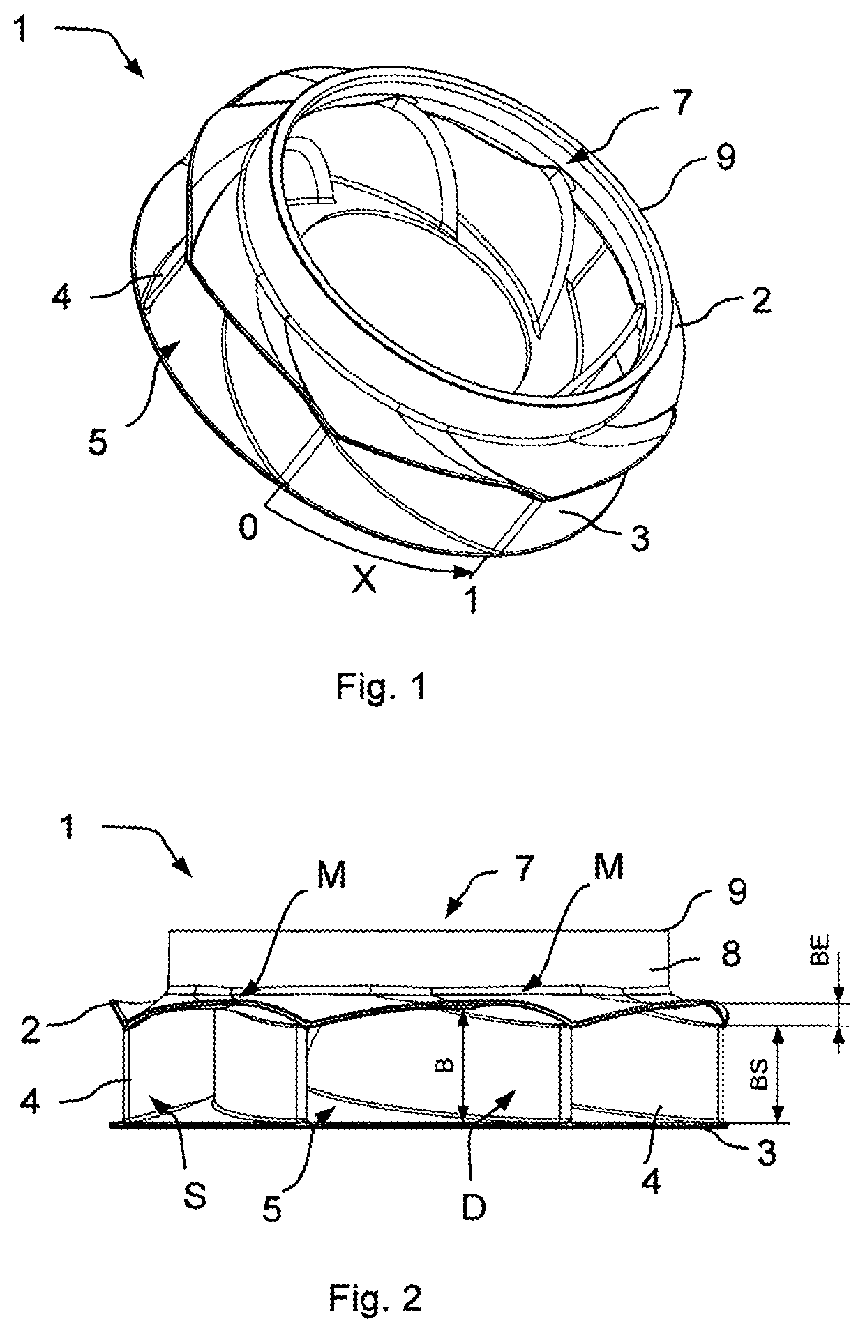
[0024]FIGS. 1 and 2 show an exemplary embodiment of a radial fan wheel 1 having a plurality of fan wheel blades 4 arranged in a blade ring and curved backwards, the lower axial front sides of which are completely covered by the bottom plate 3 extending parallel to an axial plane running perpendicularly opposite the rotational axis of the radial fan wheel 1. On the axially opposite front side, the fan wheel blades 4 are partially covered by the suction side cover plate 2, wherein the fan wheel blades 4 are exposed in an area of the suction opening 7 of the radial fan wheel 1 and extend towards the bottom plate 3 with an arcuate radial leading edge. The suction opening 7 is formed by the circular periphery 9. Each pair of adjacent fan wheel blades 4 forms a blade channel 5 therebetween, the flow cross section of which is determined and limited by the fan wheel blades 4, the planar bottom plate 3 and the cover plate 2. In the illustrated embodiment, all fan wheel blades 4 are identical...


PUM


Abstract

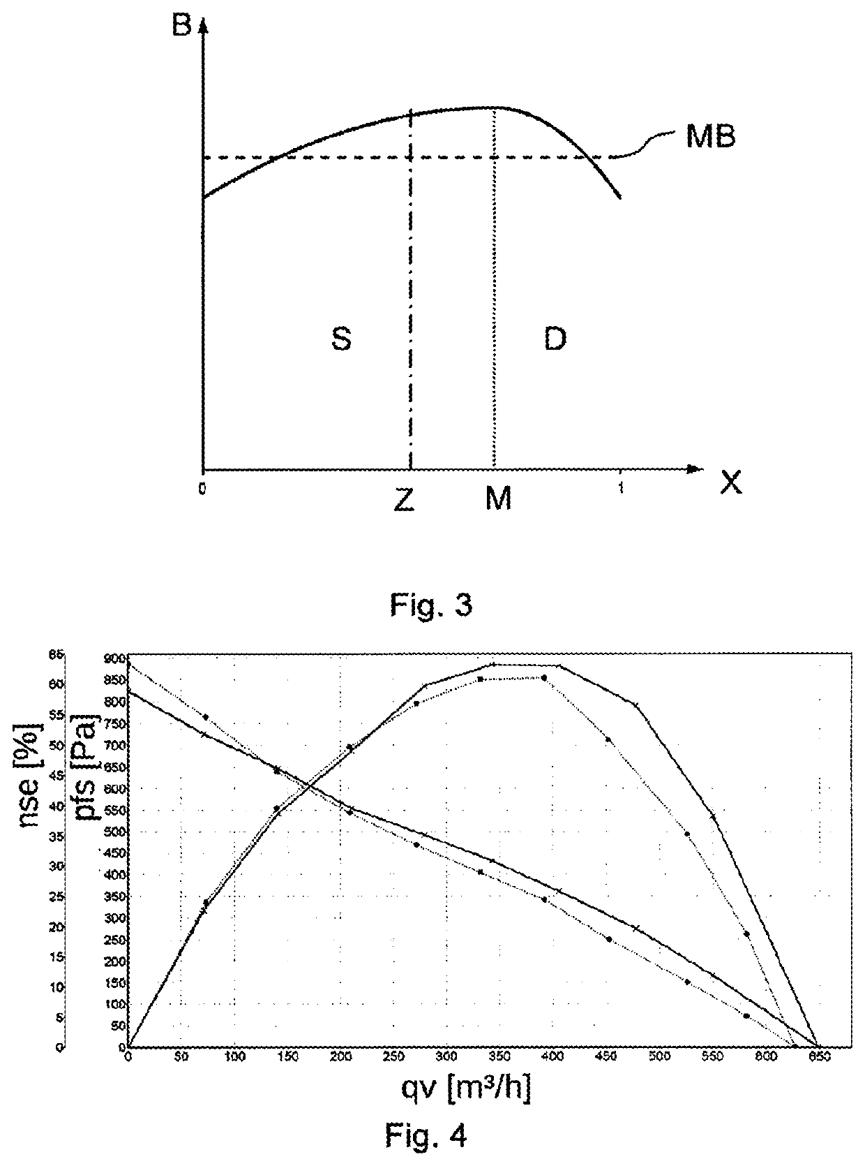
The present disclosure relates to a radial fan wheel having a plurality of fan wheel blades arranged in a blade ring and at least one plate that, at least in sections, covers the fan wheel blades axially on the front side, wherein two adjacent fan wheel blades form a blade channel therebetween, the flow cross section of which is axially limited by the plate; an axial width of the blade channel increases to a maximum (M) at least along an outer periphery of the radial fan wheel starting from a suction side (S) of a fan wheel blade limiting the blade channel in the direction of a pressure side (D) of the adjacent fan wheel blade limiting the blade channel; wherein the maximum lies on a radial section of the fan wheel, which radial section lies between 55 and 95% of the distance between the suction side (S) of the fan wheel blade limiting the blade channel and the pressure side (D) of the adjacent fan wheel blade limiting the blade channel such that the plate, when viewed in the circumferential direction, has an asymmetrical shape between two adjacent fan wheel blades.

Description

RELATED APPLICATIONS[0001]This application claims priority to German Patent Application No. 10 2017 120 537.3, filed Sep. 6, 2017, and PCT / EP2018 / 072693, filed Aug. 22, 2018, the entire contents of which are incorporated herein by reference in their entirety.FIELD[0002]The present disclosure relates to a radial fan wheel having a plurality of fan wheel blades arranged in a blade ring and at least one plate that, at least in sections, covers the fan wheel blades axially on the front side.BACKGROUND[0003]Radial fan wheels are known in the prior art in various implementations and are used in a variety of fans for different purposes. In this context, it is also known that flow separations are to be avoided as much as possible as they reduce the efficiency of the fans or blowers and cause an increase in noise generation. Typically, the suction side of the fan wheel blades is prone to flow separations in use due to overloading of the boundary layers while the flow abuts the pressure side ...

Claims


Application Information

Patent Timeline
Patent Type & Authority Applications(United States)
IPC IPC(8): F04D29/28F04D29/66
CPCF04D29/4226F04D29/667F04D29/023F04D29/281F04D29/666F05D2250/70
Inventor MÜLLER, JENSGEBERT, DANIEL
Owner EBM PAPST MULFINGEN GMBH & CO KG
Learn More