Method and device for controlling an automatic transmission

a technology of automatic transmission and control device, which is applied in the direction of gearing control, gearing elements, gearing, etc., can solve the problems of high noise level and vibration transmission into the vehicle interior, further reducing the output torque, and still generating intrusive idle vibrations, etc., to achieve low input torque, facilitate rotation, and facilitate the effect of starting and stopping

Inactive Publication Date: 2011-05-24
FORD GLOBAL TECH LLC
View PDF6 Cites 4 Cited by
  • Summary
  • Abstract
  • Description
  • Claims
  • Application Information

AI Technical Summary

Benefits of technology

[0009]According to a preferred embodiment of the invention the actuation of the brake band and the brake coupling is maintained until the turbine speed is zero. This serves in particular to avoid an otherwise frequently observed and unwanted forwards movement of the vehicle on leaving the idling mode of operation, which is also referred to as “neutral idle exit jerk” and which derives from the inertial effect of a rapid turbine speed reduction, shortly before the internal combustion engine begins to generate the drive torque. A braking of the moment of inertia of the turbine leads to an acceleration of the moment of inertia of the vehicle, if the two are engaged via the input clutch. According to the invention this effect is avoided if the brake band and the brake coupling remain actuated until the turbine speed is zero rpm. Since there is not yet any clutch connection between the turbine and the vehicle during this braking phase, a further positive effect is that the input clutch can be swiftly locked without any further control, which gives the vehicle a more rapid starting facility. According to the aforementioned preferred embodiment of the invention, therefore, the inertial torque is supported by the brake band and the brake coupling, since remain actuated until the turbine speed is zero.
[0010]According to a further preferred embodiment the turbine is rotated for at least some of the time during the simultaneous actuation of the brake band and the brake. This rotation of the speed the turbine may be performed, in particular, at a speed which is 80 to 100 rpm, preferably about 90 rpm, lower than the idling speed of the internal combustion engine. The input shaft and the turbine therefore have the facility to rotate, which allows a low input torque. The rotating turbine also means that the vibrations occurring on the engine support bracket are also low. Due to the low loads acting on the engine support bracket and the low engine vibrations, the “noise, vibration and harshness” (NVH) effects can also be substantially reduced or minimized. In the same way any unwanted acceleration from rest can be prevented and any starting delay minimized.
[0011]According to a further preferred embodiment a clutch is provided for coupling a planet carrier of the single-stage planetary gear train to the small sun gear of the two-stage planetary gear train, the simultaneous actuation of the brake band and the brake coupling occurring at least some of the time with the clutch slipping. This slipping input clutch means that the engine torque can be low. The output torque is zero, and the loads acting on the engine support bracket are low.
[0012]According to a further preferred embodiment of the invention the input clutch is temporarily fully opened, in order to allow a slight rotation of gear wheels of the two-stage planetary gear train, and thereby to remove any residual loads from the shift position preceding the “NIC” by relieving the axle half-shafts acting as torsion springs.
[0013]According to a further preferred embodiment of the invention the simultaneous actuation of the brake band and the brake coupling occurs only when the vehicle is stationary. In particular, an enhanced safeguard against accidental locking of the transmission gear wheels at high vehicle speeds is preferably achieved, which as explained below can be obtained by a dual or redundant monitoring of the output speed.
[0014]Here a sensor device, which generates a sensor signal only when the vehicle is stationary, is preferably used in order to ensure that a simultaneous actuation of the brake band and the brake coupling occurs only when the vehicle is stationary. This has the advantage that in order to provide the safeguard function a simultaneous activation of the brake band and the brake coupling can be prevented even in the event of a defective speed sensor.

Problems solved by technology

These loads acting on the axle shafts and the engine support brackets lead to a high noise level and to the transmission of vibrations into the vehicle interior via the struts and the vehicle body.
Since load reduction by means of the NI method has proved inadequate, a further additional measure taken has been to shift into second gear whilst idling in the “D” drive position of the transmission, thereby further reducing the output torque.
Even with this additional measure, however, intrusive idling vibrations are still generated.
Although shifting even higher, i.e. into third gear, has also been considered, this may have negative effects on the rollback behavior when negotiating a gradient and can also lead to jerky starting and to a reduction in the service life of the input clutch, since in third gear rapid internal rotations occur in the transmission.

Method used


Image

  • Method and device for controlling an automatic transmission
  • Method and device for controlling an automatic transmission
  • Method and device for controlling an automatic transmission

Examples


Embodiment Construction

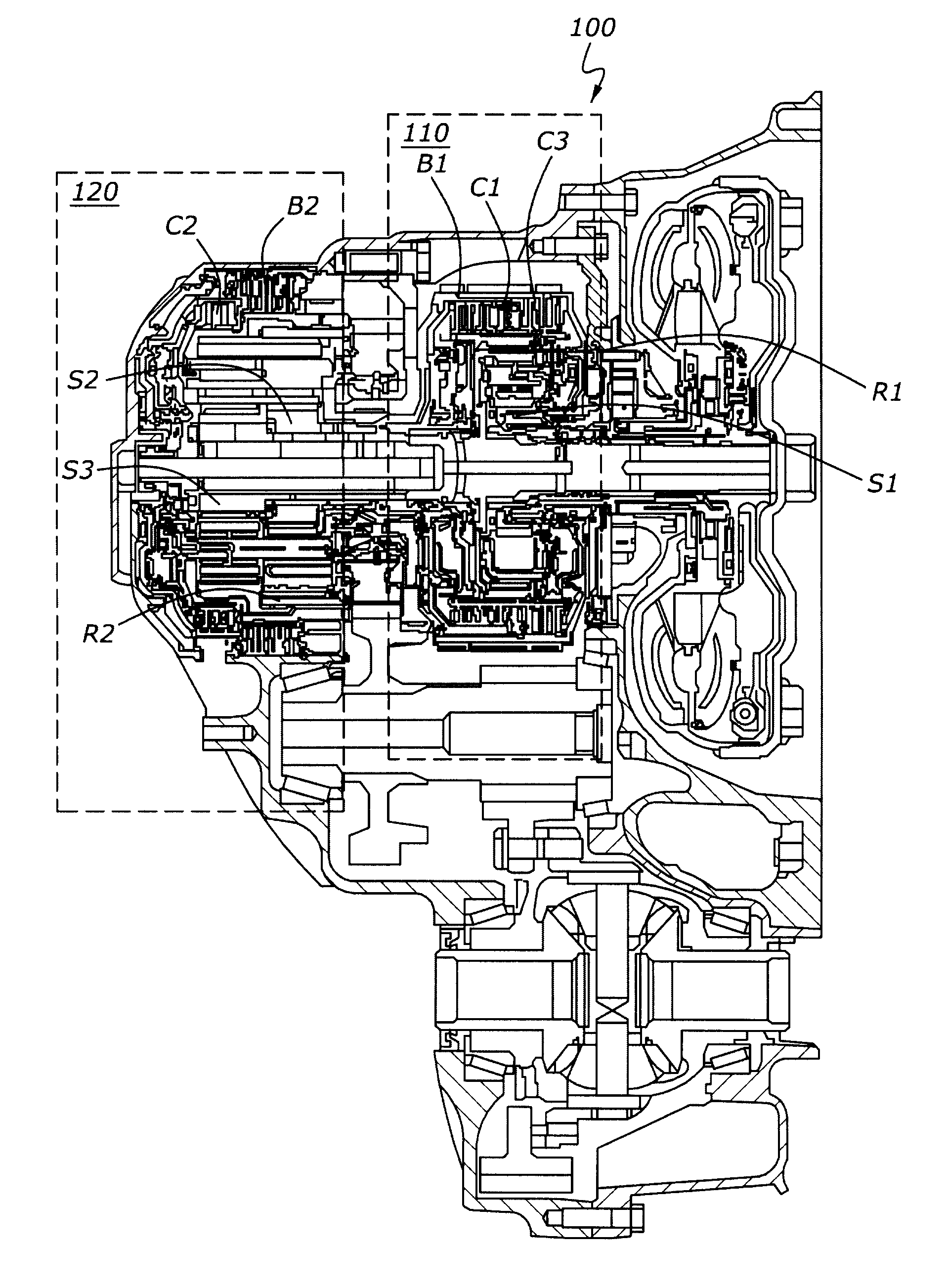
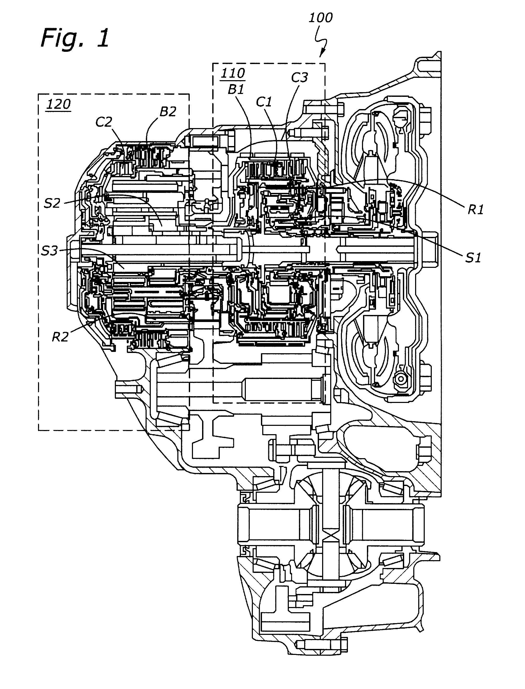
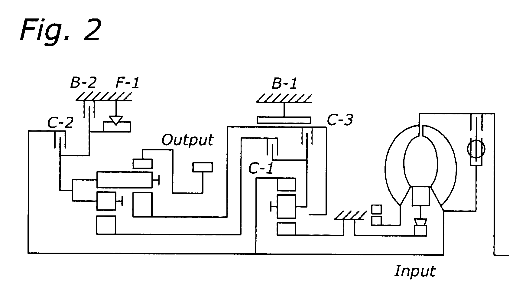
[0024]The inventive method and device for controlling an automatic transmission are embodied in a six-speed automatic transmission 100, represented schematically in FIGS. 1 and 2, which combines a single-stage planetary gear train 110 with a two-stage planetary gear train or a Ravigneaux train 120. This known construction is also referred to as a “Le Pelletier” type. FIG. 1 here shows a cross sectional view of the structure of the transmission and FIG. 2 shows a schematic representation of the gear train.

[0025]In the structure according to FIG. 1 the single-stage planetary gear train 110 serves as speed-reduction or step-down transmission and has a sun gear S1, a ring gear R1, planetary gears and a planet carrier. The sun gear S1 is permanently fixed. The ring gear R1 is connected to the turbine shaft.

[0026]The two-stage planetary gear train 120 or the Ravigneaux train has a rear, (small) sun gear S3, a front (large) sun gear S2, a ring gear R3, short planetary gears, long planetary...


PUM


Abstract

The invention relates to a method and a device for controlling an automatic transmission, the automatic transmission (100) comprising a single-stage planetary gear train (110) in combination with a two-stage planetary gear train (120), and provision being made for a brake band (B1) assigned to the large sun gear of the two-stage planetary gear train (110) and a brake coupling (B2) assigned to the planet carrier of the two-stage planetary gear train (120). In order to reduce idling vibrations, the brake band (B1) and the brake coupling (B2) are actuated simultaneously for at least some of the time during an operating state in which the internal combustion engine is idling.

Description

FIELD OF THE INVENTION[0001]The invention relates to a method and a device for controlling an automatic transmissionBACKGROUND OF THE INVENTION[0002]It is nowadays generally necessary in diesel-powered motor vehicles with automatic transmission to take measures in order to reduce idling vibrations when the automatic transmission is in the “D” (“Drive”) position. This is usually done via a method of control referred to as NI or NIC control (NIC=“neutral idle control”), in which the torque transmission from the converter turbine to the transmission and onwards to the drive shafts is reduced by means of a slipping input clutch. This is also referred to in the case of a six-speed automatic transmission of the so-called “Le Pelletier” type as a C1 clutch. The slipping C1 clutch enables the turbine to rotate at a speed approximately 90 rpm below the idling speed of the internal combustion engine, thereby reducing the converter output torque. The output torque to the axle shafts is then ap...

Claims


Application Information

Patent Timeline
Patent Type & Authority Patents(United States)
IPC IPC(8): F16H31/00
CPCF16H61/0059F16H61/20Y10T477/644F16H2057/0012Y10T477/6388F16H2061/207
Inventor TAAL, MARTIN BASTIAAN
Owner FORD GLOBAL TECH LLC
Why Eureka
Try Eureka