Combination vertical rotary vane suction pump and liquid separator

a vertical rotary vane suction pump and liquid separator technology, which is applied in the direction of centrifugal force sediment separation, rotary piston liquid engine, machine/engine, etc., can solve the problems of constant supply, significant water utility fees for the end user, and still have setbacks

Inactive Publication Date: 2011-05-24
GAST MFG
View PDF35 Cites 5 Cited by
  • Summary
  • Abstract
  • Description
  • Claims
  • Application Information

AI Technical Summary

Benefits of technology

The invention relates to a new design for a vacuum pump that allows easy maintenance without having to replace its bearings. This is achieved by supporting the rotor with a single-sided attachment system, which makes it possible to easily inspect and repair any issues with the pump's vanes. A unique feature is also included where the top part of the pump can be removed while keeping the rest of the components intact, making service even more convenient.

Problems solved by technology

The technical problem addressed in this patent text is the need for an improved suction system that is cost-efficient, compact, and can provide comparable or better performance compared to prior art devices. The system should also be applicable to various fields beyond dental applications, such as any application requiring solid and/or liquid suction.

Method used


Image

  • Combination vertical rotary vane suction pump and liquid separator
  • Combination vertical rotary vane suction pump and liquid separator
  • Combination vertical rotary vane suction pump and liquid separator

Examples


Embodiment Construction

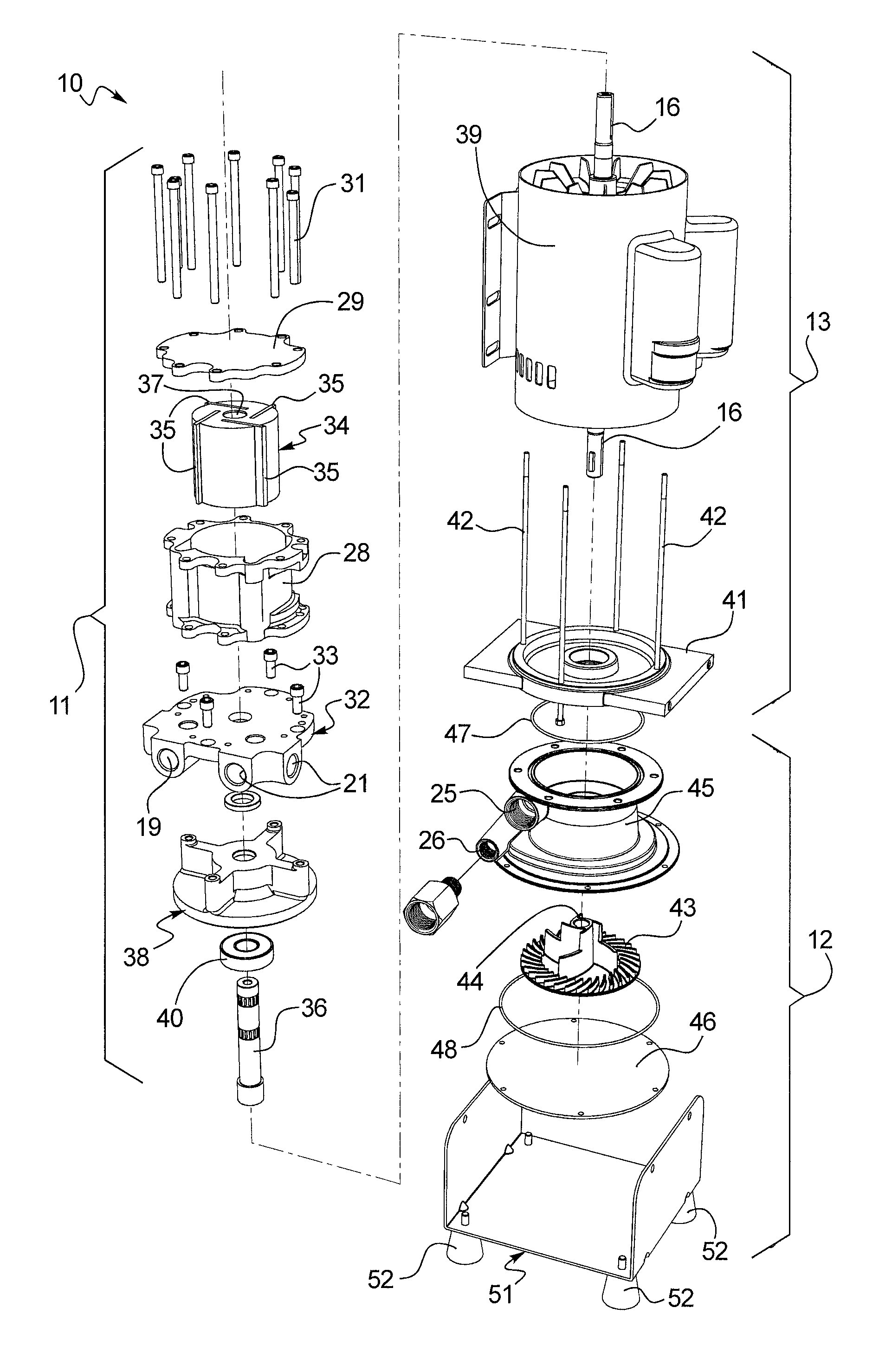
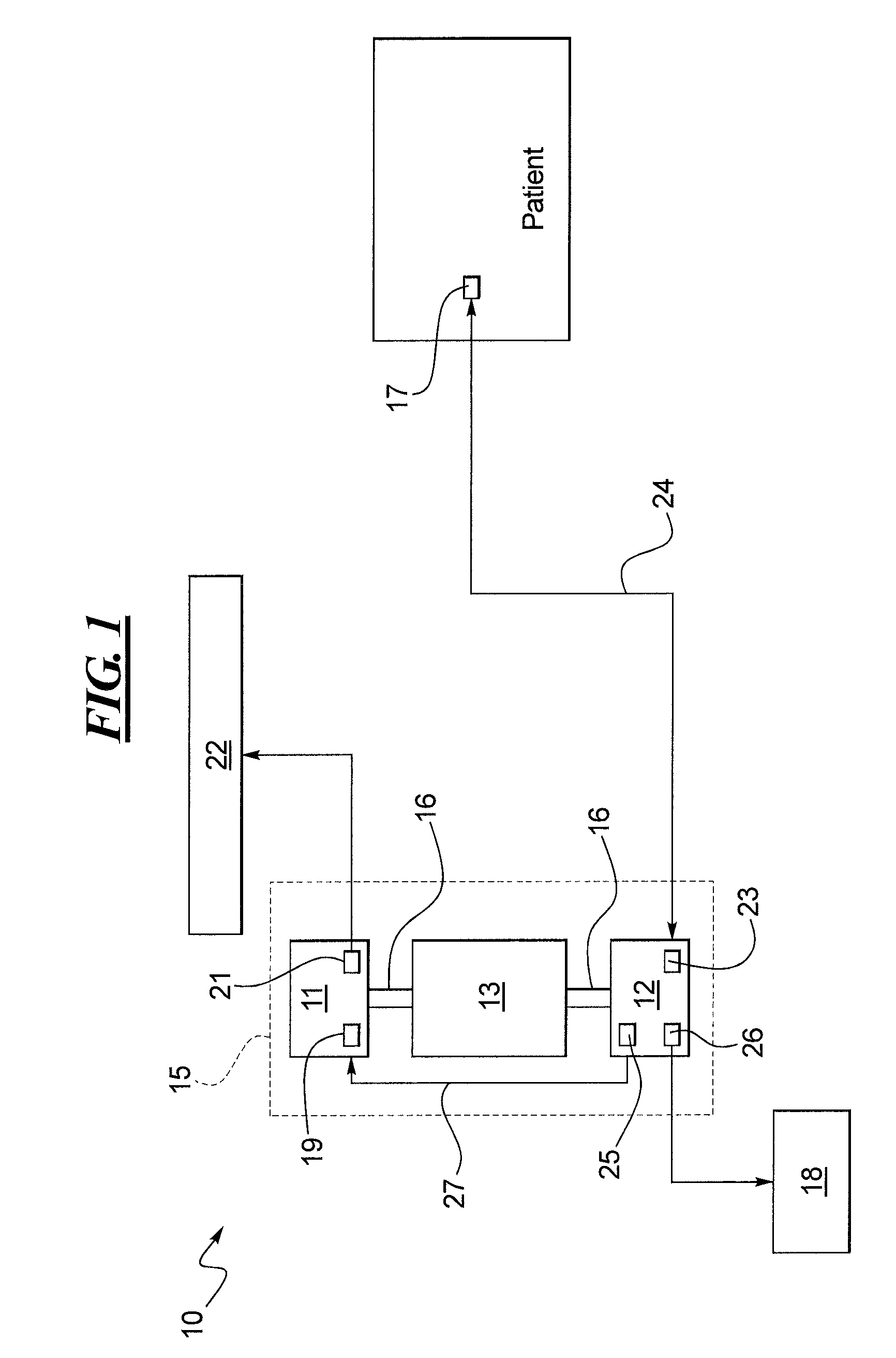
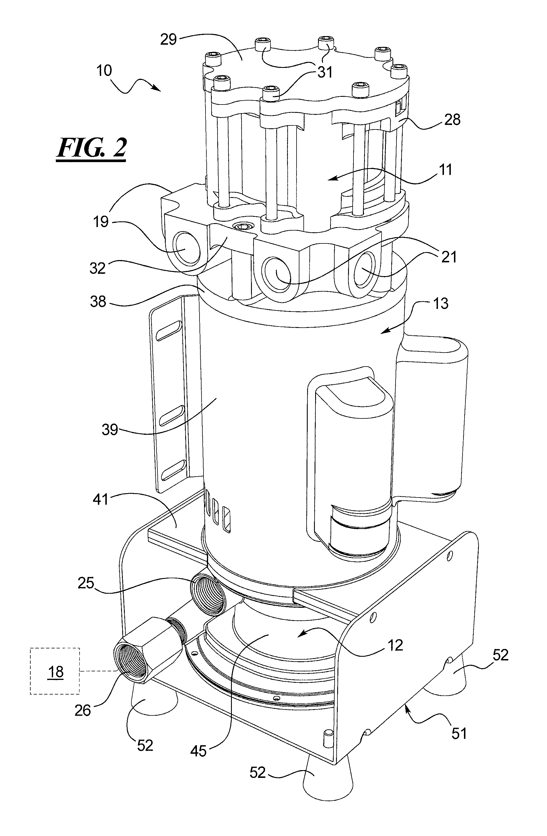
[0043]FIG. 1 illustrates a diagrammatic view of a disclosed combination suction / liquid separator 10 as configured for use with a typical dental application. As shown in FIG. 1, the combination suction / liquid separator 10 may include a pump 11, a liquid separator 12 and a motor 13 for operating the pump 11 and the separator 12. The suction / liquid separator 10 may optionally include an enclosure 15 so as to reduce noise caused by operating the device 10. The pump 11 may comprise any pump or blower configuration commonly known in the art to create a vacuum or suction, for example, a rotary vane pump. The liquid separator 12 may be configured to be an automatic separator that uses gravity to passively separate solids and / or liquids from air or other gases. Alternatively, the liquid separator 12 may be configured to include a mechanical or spinning disk separator to actively separate solids and / or liquids from air. The motor 13 may be, for example, an induction motor, or any other motor ...


PUM


Abstract

A compact suction and separation device is shown and described. The suction and separation device includes a pump and a separator. The pump includes a vertically oriented rotary vane pump comprising a suction inlet and an exhaust outlet. The separator includes a collector configured to receive combinations of solids, liquids and air. The separator separates solids and/or liquids from the air. Air from the separator is routed from an air discharge into the suction inlet of the pump. Solids and/or liquids are drained from a liquids/solids discharge of the separator. The separator may be gravity-based or centrifuge-type separator driven by the pump motor.

Description


Claims


Application Information

Patent Timeline
Owner GAST MFG
Why Eureka
Try Eureka