Ejector cycle system

a technology of ejector cycle and evaporator, which is applied in the direction of gas cycle refrigeration machines, refrigeration machines, corrosion prevention, etc., can solve the problem of inability to perform defrosting operation of evaporators

Inactive Publication Date: 2003-07-01
DENSO CORP
View PDF9 Cites 45 Cited by
  • Summary
  • Abstract
  • Description
  • Claims
  • Application Information

AI Technical Summary

Benefits of technology

It is an another object of the present invention to provide an ejector cycle system which can substantially perform a defrosting operation of an evaporator.
It is a further another object of the present invention to provide an ejector cycle system which can shorten a defrosting time period.
According to the present invention, an ejector cycle system includes a compressor for sucking and compressing refrigerant, a radiator which cools refrigerant discharged from the compressor, an evaporator for evaporating the refrigerant to obtain cooling capacity, a gas-liquid separator having a gas refrigerant outlet coupled to a refrigerant suction side of the compressor and a liquid refrigerant outlet coupled to a side of the evaporator, and an ejector. The ejector includes a nozzle for converting a pressure energy of high-pressure refrigerant from the radiator to a speed energy so that the high-pressure refrigerant is decompressed and expanded, and a pressure-increasing portion in which the speed energy is converted to the pressure energy so that the pressure of refrigerant is increased while refrigerant discharged from the nozzle and gas refrigerant from the evaporator are mixed. In the ejector cycle system, refrigerant discharged from the compressor is introduced into the evaporator while bypassing the ejector and the gas-liquid separator, in a defrosting operation for defrosting frost generated on the evaporator. Accordingly, it can prevent liquid refrigerant in the gas-liquid separator from flowing into the evaporator in the defrosting operation. Therefore, the defrosting operation can be effectively performed, and a defrosting time period for which the defrosting operation is performed can be made shorter. That is, the ejector cycle system has an improved refrigerant passage structure for performing the defrosting operation of the evaporator.
Preferably, a pressure-loss generating unit for generating a predetermined pressure loss is disposed in a refrigerant passage through which the liquid refrigerant outlet of the gas-liquid separator communicates with the evaporator. For example, the pressure-loss generating unit is a throttle member, or a valve which adjusts an opening degree of the refrigerant passage to generate a predetermined pressure loss in the refrigerant passage. Therefore, hot gas refrigerant discharged from the compressor can be accurately flows into the evaporator through a bypass passage without flowing toward the gas-liquid separator.
Preferably, a check valve is disposed in the refrigerant passage through which the liquid refrigerant outlet of the gas-liquid separator communicates with the evaporator, to prohibit a refrigerant flow from the evaporator toward the gas-liquid separator through the refrigerant passage. Therefore, the defrosting operation of the evaporator can be accurately performed using hot gas refrigerant introduced into the evaporator through the bypass passage.
Further, an another gas-liquid separator is disposed in a refrigerant passage connecting the evaporator and the ejector, and has a refrigerant outlet from which the gas refrigerant separated in the another gas-liquid separator is sucked into the ejector. Therefore, hot gas refrigerant from the compressor is introduced into the evaporator through the bypass passage in the defrosting operation to heat the evaporator so that refrigerant (liquid refrigerant) staying in the evaporator is discharged outside the evaporator. In this case, liquid refrigerant among the refrigerant flowing from the evaporator stays in the another gas-liquid separator, and gas refrigerant separated in the another gas-liquid separator is sucked into the ejector. Thus, operation of the ejector cycle system with the ejector can be effectively performed.

Problems solved by technology

However, in the ejector cycle system, it is impossible to perform defrosting operation of the evaporator.

Method used


Image

  • Ejector cycle system
  • Ejector cycle system
  • Ejector cycle system

Examples


first embodiment

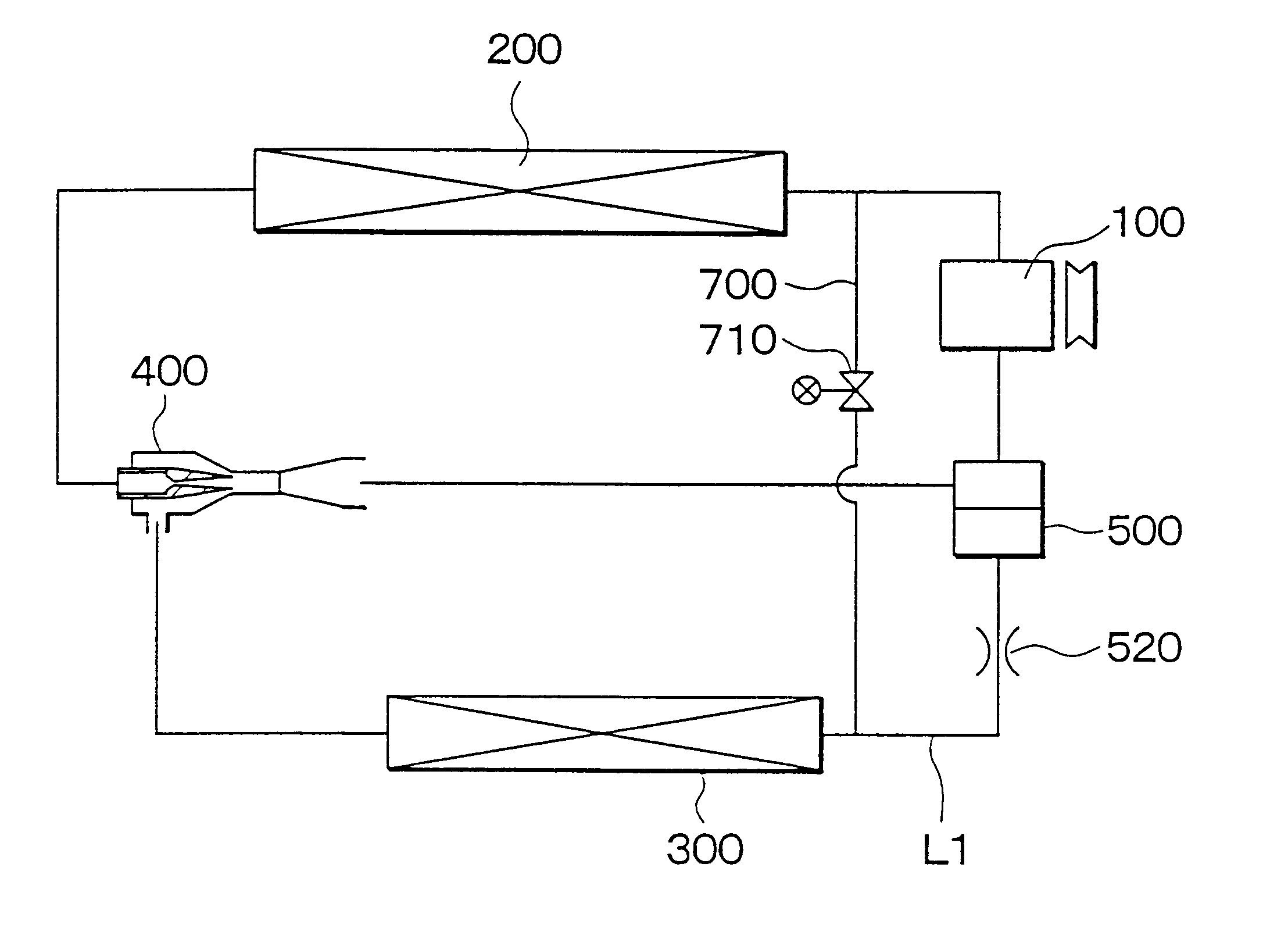
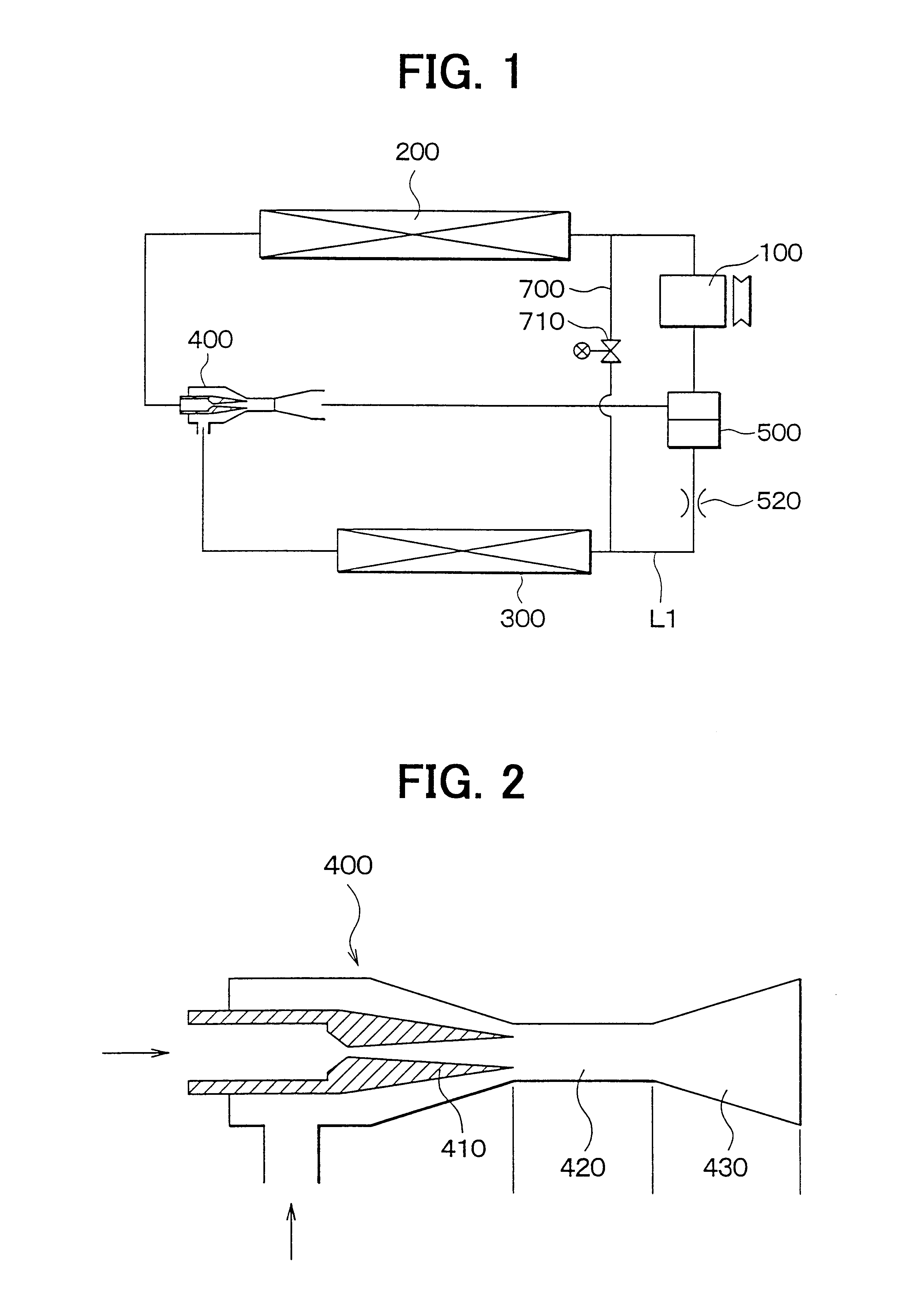
A first preferred embodiment of the present invention will be now described with reference to FIGS. 1-3. In the first embodiment, an ejector cycle system of the present invention is typically used for a vehicle air conditioner.

In the first embodiment, a compressor 100 is driven by a driving source such as a vehicle engine (not shown) to suck and compress refrigerant (e.g., carbon dioxide in the first embodiment). In a radiator 200 (i.e., high-pressure side heat exchanger), refrigerant discharged from the compressor 100 is heat-exchanged with air (outside air) outside a passenger compartment. In an evaporator 300 (i.e., low-pressure side heat exchanger), liquid refrigerant in the ejector cycle system is heat-exchanged with air to be blown into a passenger compartment to cool air. An ejector 400 decompresses and expands high-pressure refrigerant flowing from the radiator 200 to suck therein gas refrigerant evaporated in the evaporator 300, and converts an expansion energy to a pressur...

second embodiment

the present invention will be now described with reference to FIG. 4. In the second embodiment, instead of the fixed throttle 520, a check valve 510 is provided in the refrigerant passage L1. The check valve 510 is disposed to allow a direct refrigerant flow from the gas-liquid separator 500 to the evaporator 300, and to prohibit a direct refrigerant flow from the evaporator 300 to the gas-liquid separator 500. Accordingly, in the defrosting operation of the evaporator 300, hot gas refrigerant discharged from the compressor 100 can be accurately introduced into the evaporator 300.

Further, in the second embodiment, the refrigerant passage L1 is set to generate a predetermined pressure loss while refrigerant flow, in order to reduce the pressure of refrigerant sucked into the evaporator 300 and to accurately reduce the pressure (evaporation pressure) in the evaporator 300. For example, the refrigerant passage L1 can formed by a capillary tube or can be provided with a fixed throttle. ...

third embodiment

the present invention will be now described. In the third embodiment, a three-way valve 710a is further provided in a joint portion where the hot gas passage 700 and the refrigerant passage L1 are joined. Accordingly, in the defrosting operation of the evaporator 300, high-temperature refrigerant discharged from the compressor 100 can be accurately introduced into the evaporator 300 through the three-way valve 710a. In the third embodiment, a decompression unit for decompressing refrigerant can be provided in the three-way valve 710a.

A fourth preferred embodiment of the present invention will be now described with reference to FIG. 6. In the fourth embodiment, instead of the fixed throttle 520 described in the first embodiment, a valve 530 that is controlled to change its opening degree is provided in the refrigerant passage L1. Specifically, the opening degree of the valve 530 can be controlled from zero to a predetermined opening degree by which a predetermined pressure loss is ge...


PUM


Abstract

In an ejector cycle system, hot gas refrigerant discharged from a compressor is introduced into an evaporator through a bypass passage while bypassing an ejector and a gas-liquid separator in a defrosting operation for defrosting frost generated on the evaporator. In addition, a throttle or a check valve is provided in a refrigerant passage from the gas-liquid separator to a refrigerant inlet side of the evaporator. Accordingly, in the defrosting operation, the hot gas refrigerant from the compressor can be accurately introduced into the evaporator through the bypass passage without flowing toward the gas-liquid separator.

Description

This application is related to Japanese Patent Applications No. 2001-206683 filed on Jul. 6, 2001, and No. 2002-150786 filed on May 24, 2002, the contents of which are hereby incorporated by reference.1. Field of the InventionThe present invention relates to an ejector cycle system having an improved refrigerant passage structure.2. Description of Related ArtIn an ejector cycle System described in JP-A-6-11197, an ejector sucks gas refrigerant evaporated in an evaporator at a low pressure side, and increases a pressure of refrigerant to be sucked into a compressor by converting an expansion energy to a pressure energy. In the ejector cycle system, refrigerant discharged from the ejector flows into a gas-liquid separator, so that liquid refrigerant separated in the gas-liquid is supplied to the evaporator, and gas refrigerant separated in the gas-liquid separator is sucked into the compressor. Accordingly, the refrigerant cycle system has a refrigerant flow circulating through the co...

Claims


Application Information

Patent Timeline
Patent Type & Authority Patents(United States)
IPC IPC(8): F25B41/00F25B47/02F25B9/00F25B9/08F25B1/00
CPCF25B41/00F25B47/022F25B9/008F25B2309/06F25B2341/0012F25B2400/04F25B9/08
Inventor TAKEUCHI, HIROTSUGUIKEGAMI, MAKOTO
Owner DENSO CORP
Why Eureka
Try Eureka