Fixing device, fixing device temperature control method and image forming apparatus

a fixing device and temperature control technology, applied in the direction of electrographic process equipment, instruments, optics, etc., can solve the problems of unstable fixed image performance, difficult to stably adjust the and the surface temperature of the heating and fixing roller and the detection temperature of the noncontact temperature sensor. to achieve stable fixed image performance, and correct determination of the fluctuation of the detection temperatur

Inactive Publication Date: 2011-05-24
KONICA MINOLTA BUSINESS TECH INC
View PDF15 Cites 0 Cited by
  • Summary
  • Abstract
  • Description
  • Claims
  • Application Information

AI Technical Summary

Benefits of technology

[0006]An object of the present invention is to provide a fixing device capable of suppressing a temperature difference generated in noncontact temperature detecting sections, obtaining a stable fixed image performance, correctly determining the detection temperature fluctuation in the temperature detecting sections depending on the environment and stably adjusting the temperature of the heating and fixing roller, and to provide an image forming apparatus that employs the fixing device. Also, another object of the present invention is to provide a temperature control method for the fixing device.
[0014]According to the fixing device of the present invention, the second temperature detecting section is provided for detecting the temperature of the pressurizing unit placed inside the pressurizing rotation unit, and therefore, the second temperature detecting section can correctly measure the warming degree of the heating rotation unit and the pressurizing rotation unit. This is because the pressurizing unit is placed inside the pressurizing rotation unit, so that no sharp temperature change is caused by the rotation and the pressurizing unit is hard to cool.
[0015]The control section adjusts the surface temperature of the heating rotation unit by controlling the heating section on the basis of both the detection temperature of the first temperature detecting section and the detection temperature of the second temperature detecting section. Therefore, it is possible to obtain a stable temperature detection performance because the temperature difference between the surface temperature of the heating rotation unit and the detection temperature of the first temperature detecting section is corrected by the detection temperature of the second temperature detecting section which can measure the warming degree of the heating rotation unit and the pressurizing rotation unit. Also, even if the detection temperature of the first temperature detecting section is varied by the placement distance of the first temperature detecting section to the heating rotation unit, the environmental variation, the warming degree of the fixing device and the like, the variation in the detection temperature of the first temperature detecting section can correctly be determined by the detection temperature of the second temperature detecting section. Thus, the surface temperature of the heating rotation unit can stably be adjusted.
[0016]Thus, it is possible to suppress the temperature difference generated in the noncontact first temperature detecting section, and therefore to obtain a stable fixed image performance. Also, the detection temperature fluctuation in the first temperature detecting section, due to the environment and so on, is correctly determined, and therefore the surface temperature of the heating rotation unit can stably be adjusted.

Problems solved by technology

This has caused a problem that the surface temperature of the heating and fixing roller and the detection temperature of the noncontact temperature sensor differ from each other.
Accordingly, it has been difficult to stably adjust the temperature of the heating and fixing roller on the basis of the detection temperature of the noncontact temperature sensor.
Therefore, the fixed image performance has not been stable.
As the result, it has been difficult to stably adjust the temperature of the heating and fixing roller with use of only the temperature detected by the noncontact temperature sensor, since those temperature variations cannot be correctly predicted.

Method used


Image

  • Fixing device, fixing device temperature control method and image forming apparatus
  • Fixing device, fixing device temperature control method and image forming apparatus
  • Fixing device, fixing device temperature control method and image forming apparatus

Examples


first embodiment

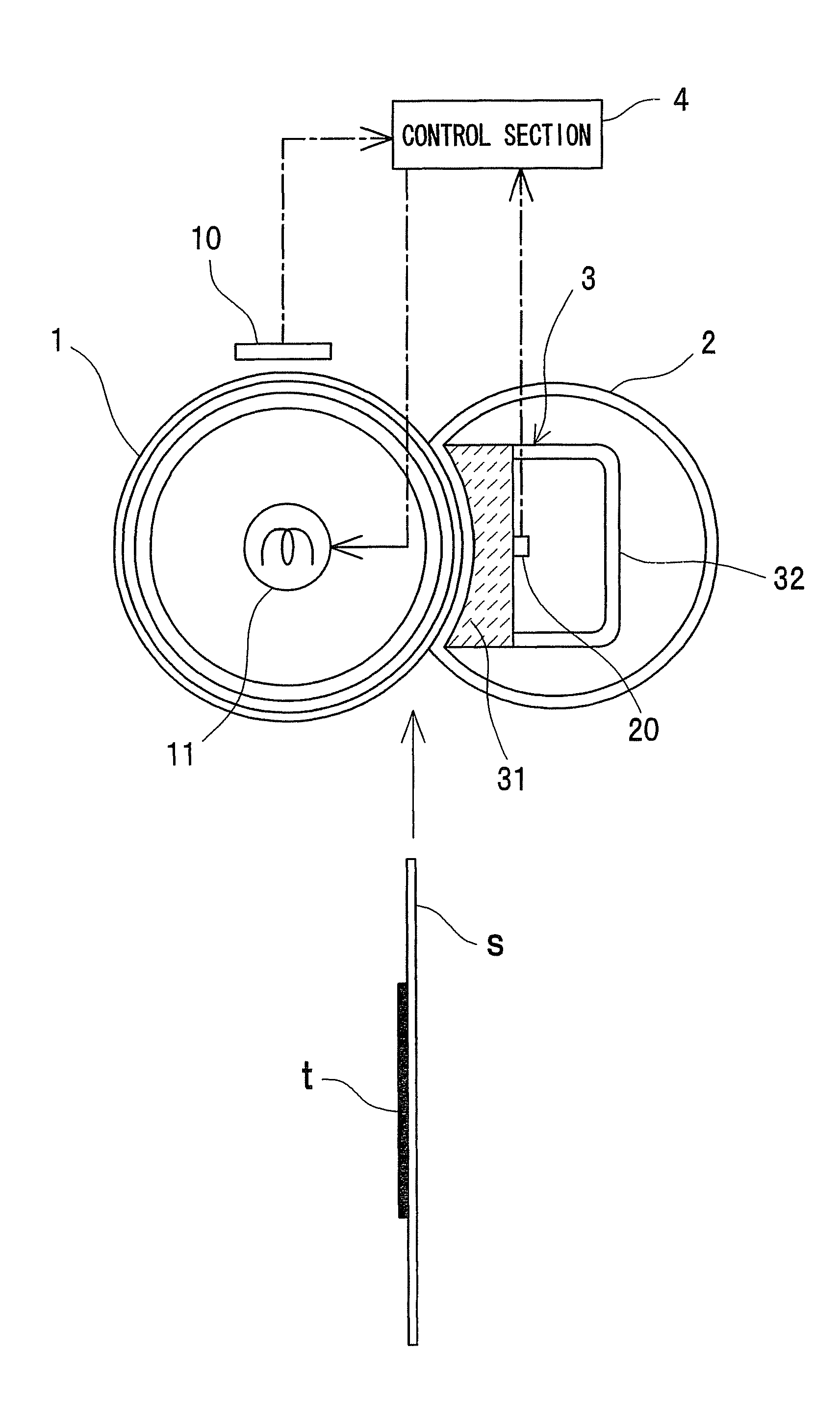
[0034]FIG. 1 shows a schematic structural view of a fixing device in a first embodiment of the present invention. The fixing device has a heating roller 1 as a heating rotation unit, and a pressure belt 2 as a pressurizing rotation unit. The heating roller 1 is heated by a heater 11 as a heating section.

[0035]The heating roller 1 and the pressure belt 2 contact each other to fix a toner t on a recording material S while conveying the recording material S. Specifically, a nip portion is formed by contacting the heating roller 1 with the pressure belt 2, and the nip portion fuses and fixes the toner t on the recording material S while conveying the recording material S.

[0036]The recording material S is, for example, a sheet of a paper, an OHP sheet or the like. The toner t adheres to one surface of the recording material S. The toner t is made of a material having a thermo-fusibility such as a resin, a magnetic material or a colorant.

[0037]The heating roller 1 is a fixing roller which...

second embodiment

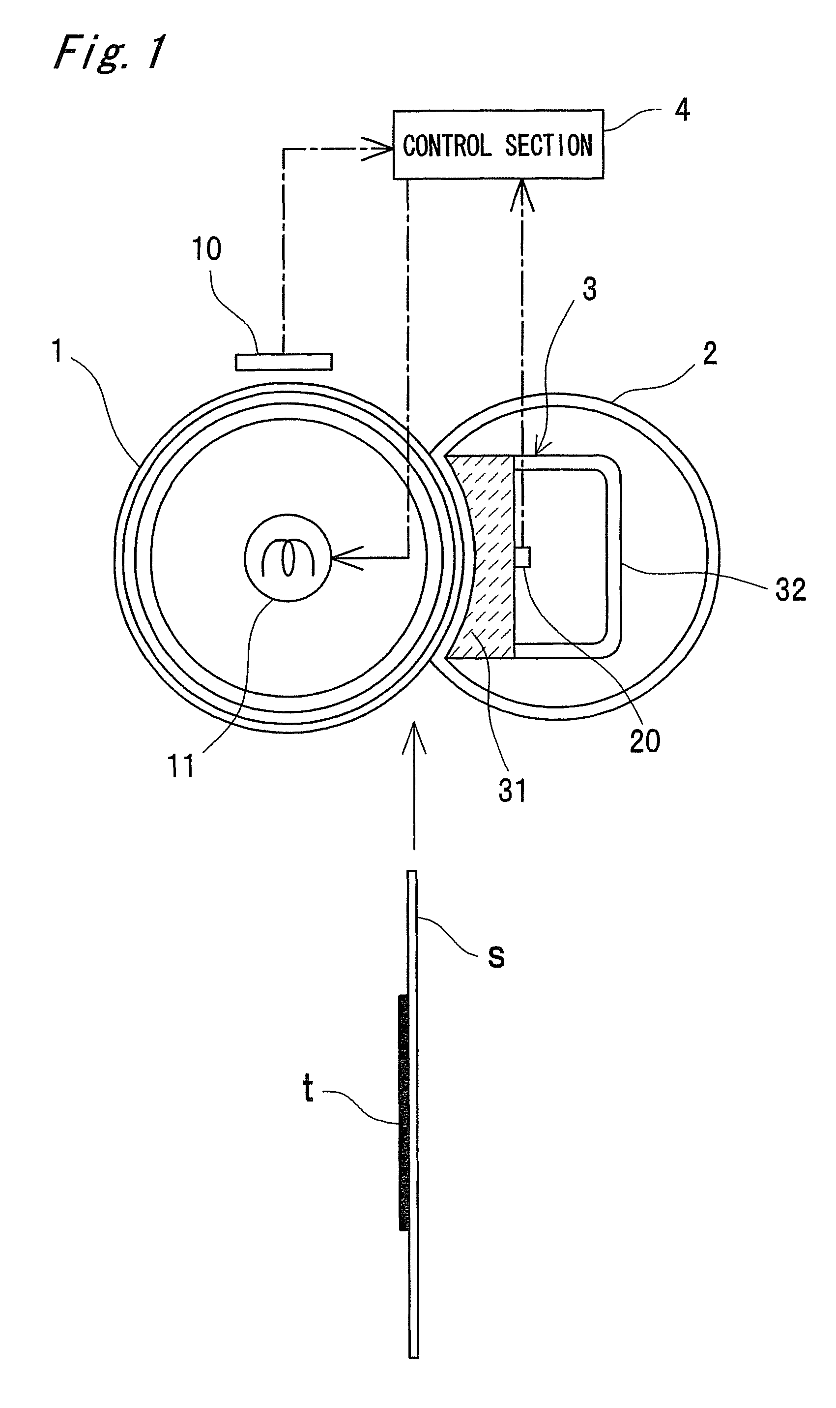
[0086]FIG. 2 shows the fixing device according to a second embodiment of the present invention. The second embodiment differs from the first embodiment in that the pressure thermistor 20 is attached to the inside of the pad portion 31.

[0087]Therefore, it is possible to firmly attach the pressure thermistor 20 to the pad portion 31. It is possible to detect the temperature of the pressure belt 2 since the pressure thermistor 20 can be brought close to the pressure belt 2.

third embodiment

[0088]FIG. 3 shows the fixing device according to a third embodiment of the present invention. The third embodiment differs from the first embodiment in that the pressure thermistor 20 is attached to the inside of the pad portion 31 so as to come in contact with the pressure belt 2. It is noted that the pressure thermistor 20 may be attached to the reinforcing portion 32 as indicated by an imaginary line.


PUM


Abstract

A fixing device has a heating roller and a pressurizing belt which convey the a recording material in mutual contact while fixing a toner on the recording material, a heater which heats the heating roller, a noncontact first thermister which detects a surface temperature of the heating roller in a position located apart from a surface of the heating roller, a pressurizing unit which is placed inside the pressurizing belt, a second thermister which detects a temperature of the pressurizing unit; and a control section which adjusts the surface temperature of the heating roller by controlling the heater on the basis of a detection temperature of the first thermister and a detection temperature of the second thermister. Thus, fixing device is capable of suppressing a temperature difference generated in noncontact temperature detecting sections and obtaining a stable fixed image performance.

Description

CROSS-REFERENCE TO RELATED APPLICATIONS[0001]This application is based on application No. 2006-254387 filed in Japan, the entire content of which is hereby incorporated by reference.BACKGROUND OF THE INVENTION[0002]The present invention relates to a fixing device for use in, for example, a copying machine, a laser beam printer or a facsimile. The present invention also relates to a temperature control method for the fixing device, and an image forming apparatus that employs the fixing device.[0003]In a conventional fixing device, a noncontact temperature sensor has detected a surface temperature of a heating and fixing roller in a position located apart from the surface of the heating and fixing roller (refer to JP 11-223555 A).[0004]In the conventional fixing device, therefore, the noncontact temperature sensor has belatedly detected the surface temperature of the heating and fixing roller. This has caused a problem that the surface temperature of the heating and fixing roller and ...

Claims


Application Information

Patent Timeline
Patent Type & Authority Patents(United States)
IPC IPC(8): G03G15/20
CPCG03G15/2039G03G2215/2009
Inventor OTSUKA, YUTAKA
Owner KONICA MINOLTA BUSINESS TECH INC
Why Eureka
Try Eureka