Pneumatic tool with air duster

a pneumatic tool and air duster technology, applied in the direction of manufacturing tools, stapling tools, nailing tools, etc., can solve the problems of nailing work being very troublesome, nailing failure, nailing failure, etc., and achieve the effect of good operation of the pneumatic tool

a pneumatic tool and air duster technology, applied in the direction of manufacturing tools, stapling tools, nailing tools, etc., can solve the problems of nailing work being very troublesome, nailing failure, nailing failure, etc., and achieve the effect of good operation of the pneumatic tool

US7950557B2Active Publication Date: 2011-05-31MAX CO LTD

Image

  • Pneumatic tool with air duster
  • Pneumatic tool with air duster
  • Pneumatic tool with air duster

Examples


Embodiment Construction

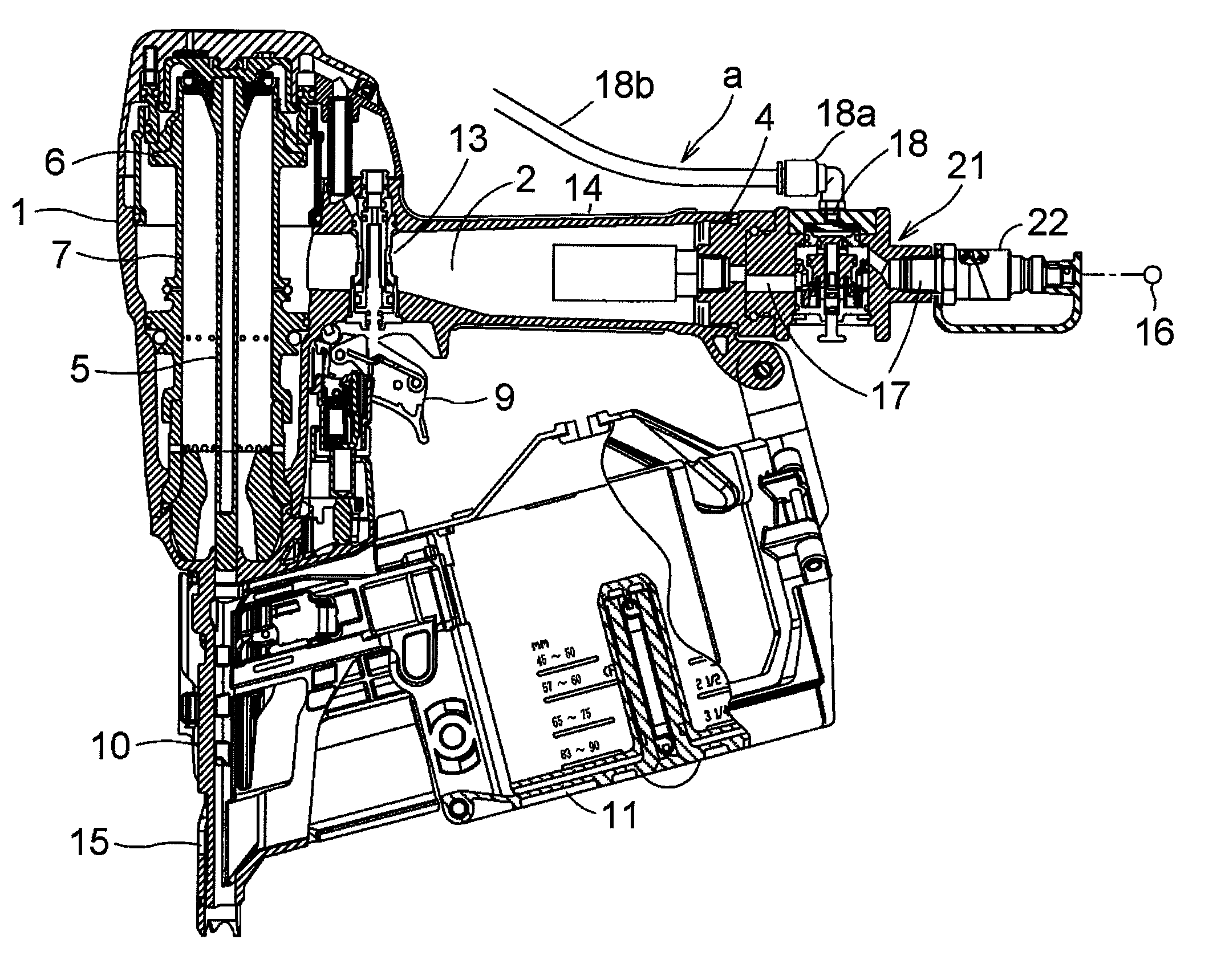
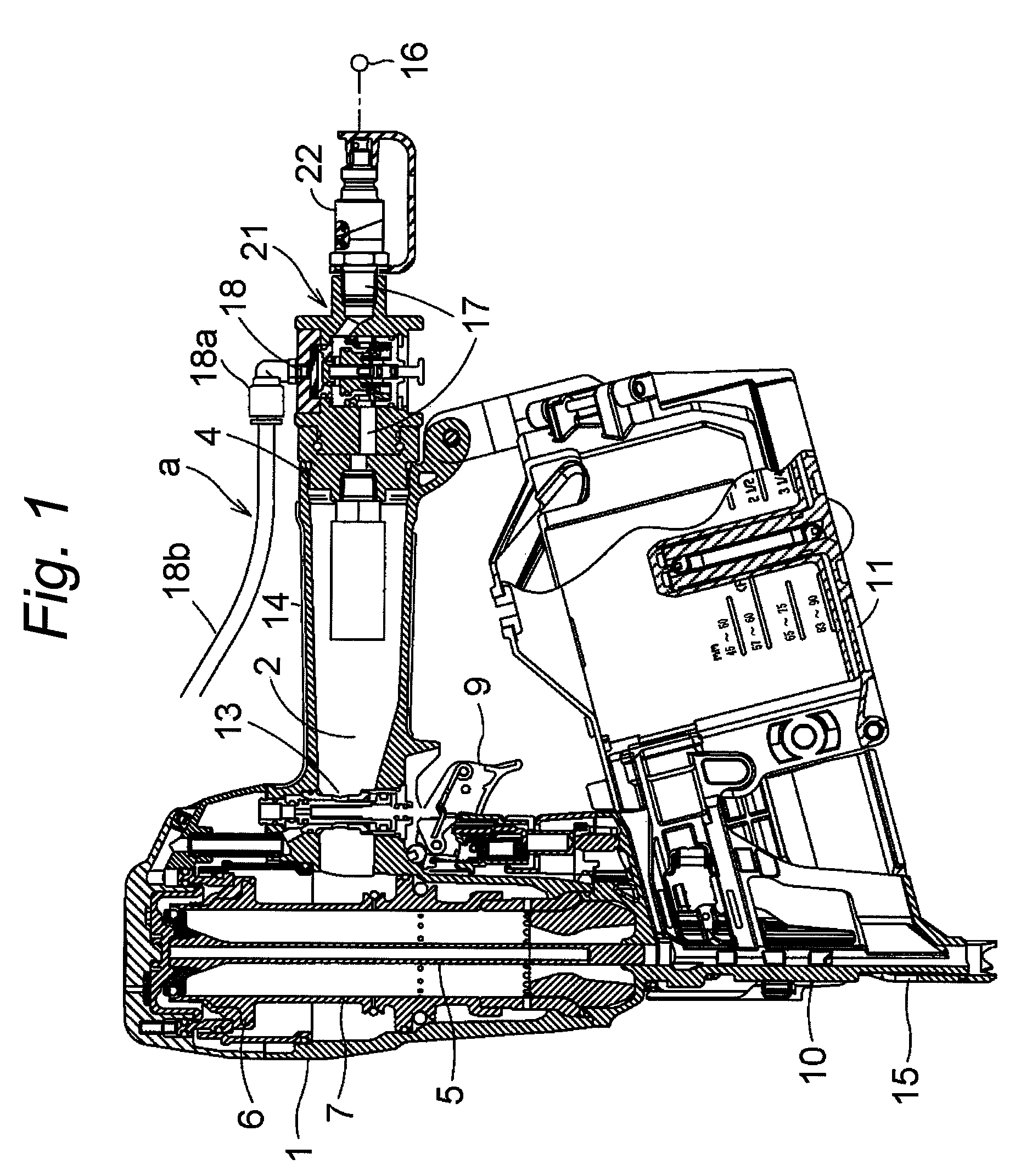
[0056]Hereinafter, an embodiment of a pneumatic tool according to the invention will be described based on the drawings using a nailing machine.

[0057]A hitting mechanism made up of a hitting piston 6 with which a driver 5 for hitting a nail by making use of compressed air accumulated within an air chamber 2 is integrally connected and a hitting cylinder 7 which accommodates the hitting piston 6 slidably or the like is provided in a nailing machine main body 1 of the nailing machine, and a nose part 10 is provided below the nailing machine main body 1 which accommodates the hitting mechanism. A magazine 11 is installed consecutively at the rear of the nose part 10 via an opening. Nails within the magazine 11 are configured to be fed sequentially to an inside of the nose part 10 by a nail supply mechanism (not shown).

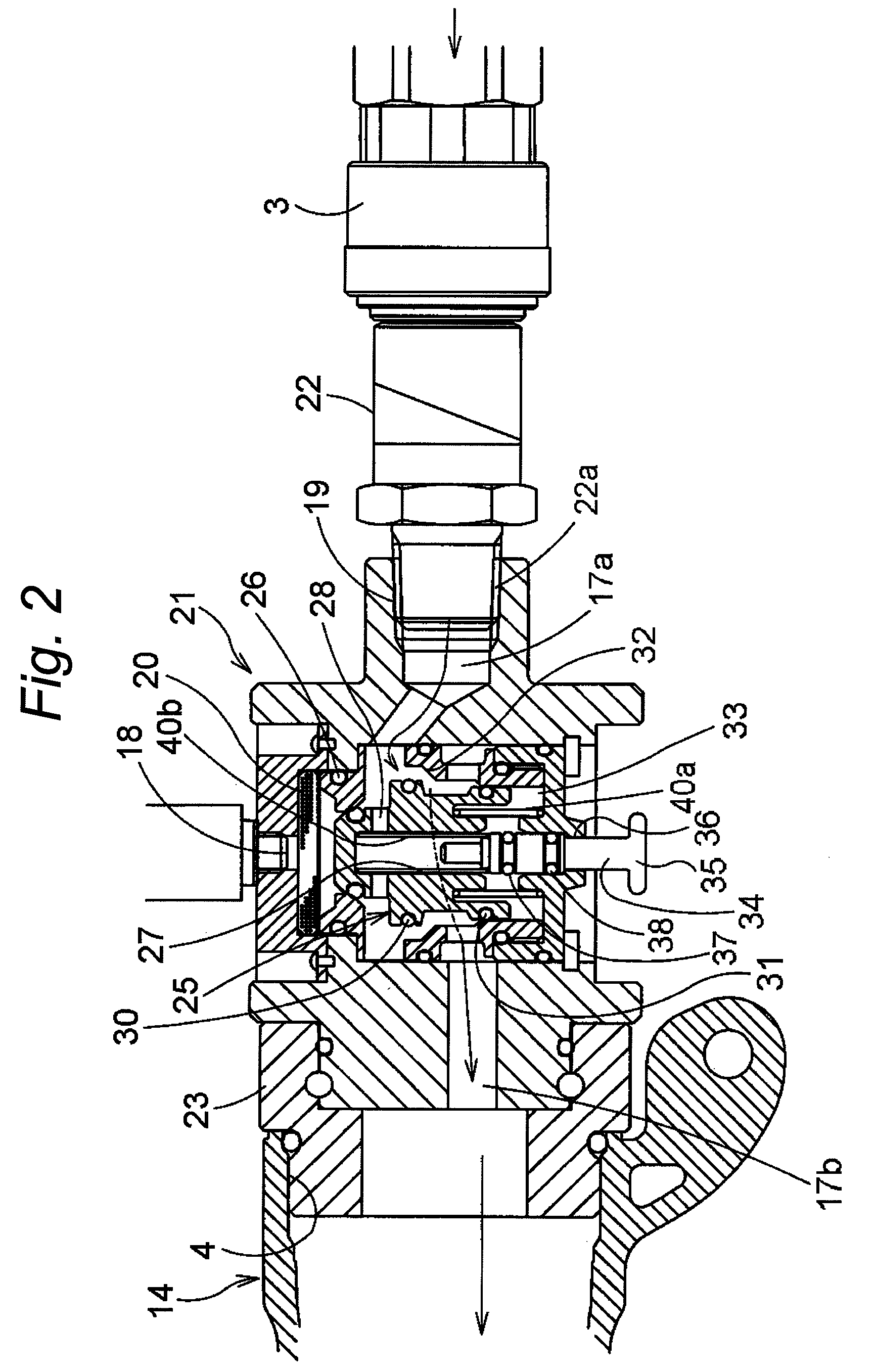
[0058]In addition, a trigger valve 13 is provided in the nailing machine man body 1 for driving the hitting mechanism so as to drive the hitting piston 6 by introducing c...


PUM

PropertyMeasurementUnit
diameteraaaaaaaaaa
pressureaaaaaaaaaa
weightaaaaaaaaaa

Abstract

An air duster duct is formed to branch off at an intermediate portion along the length of an air duct which connects a compressed air supply source with a pneumatic tool. A valve mechanism having a selector valve and an operating device is provided at the branch portion. The sector valve can shift to a first position where the selector valve opens an upstream side duct which communicates with the air supply source to a downstream side duct which communicates with a nailing machine and shuts the upstream side duct relative to the air duster branch duct and a second position where the selector valve shuts the upstream side duct relative to the down stream side duct and opens the upstream side duct to the branch duct. The selector valve is operated from the outside by the operating device.

Description

TECHNICAL FIELD[0001]The present invention relates to a pneumatic tool with an air duster in which an air duster for forcing compressed air out is attached additionally to a pneumatic tool such as a nailing machine.BACKGROUND ART[0002]For example, there happens a case where fine wood chips or shavings are found to be left on base sheets of floor materials during work of driving nails into the base sheets when making a floor. When finishing materials are laid over the base sheets with those fine wood chips or shaving left thereover as they are and then driving nails into the base sheets, the finishing materials are nailed down while being partially separated from the base sheets due to the wood chips or shavings left on the base sheets, resulting in floor making work having to be performed again. In order to prevent the occurrence of such inconveniences, finishing materials were set after surfaces of base sheets had been cleaned by an air duster for nailing work. However, since the a...

Claims


Application Information

Patent Timeline
31 May 2011
Publication
US7950557B2
IPC
B25C1/04
CPC
B25C1/047; B25C1/04
Inventors
FUJIYAMA, TAKEO; OGAWA, TATSUSHI