Feeding device and recording apparatus

a technology of feeding device and recording apparatus, which is applied in the direction of registering device, thin material processing, article separation, etc., can solve the problems of inability to align both side ends of paper with high precision, inability to perform good recording, and inability to place paper at a predetermined position

Inactive Publication Date: 2011-05-31
SEIKO EPSON CORP
View PDF7 Cites 8 Cited by
  • Summary
  • Abstract
  • Description
  • Claims
  • Application Information

AI Technical Summary

Benefits of technology

[0008]An advantage of some aspects of the invention is that it provides a feeding device which can surely align both side ends of media even in the case in which stiffness of the media is weak, and a recording apparatus including the feeding device.
[0010]According to the first aspect, the feeding device includes the curve-imparting portion. Accordingly, it is possible to curve the mounted media in the direction which intersects the moving direction of the edge guide. Further, it is possible to remarkably increase the stiffness of the mounted media in the widthwise direction of the media by curving the mounted media. As a result, when aligning both sides of the media by pushing both sides of the media with the edge guide, there is no possibility that bulking of the media occurs. Further, it is possible to surely align both ends of the media.
[0011]This advantage is particularly effective in the case in which the number of the mounted media is small and in the case in which stiffness of the media is relatively weak. That is, even if the number of media is small, the edge guide can align the media by pushing both sides of the media with the force as strong as the force in the case in which the number of media is large since the stiffness is dramatically increased. In a similar manner, even if the stiffness of the media is relatively weak, it is possible to align the media by pushing both ends of the media with the force as strong as in the case in which the stiffness of the media is relatively strong.
[0014]According to the second aspect, in addition to the same advantage of operation of the feeding device of the first aspect, the edge guide has a structure in which it is automatically moved by the driving of the motor. For example, it is structured in a manner such that as a control portion compares a current value of the motor with a predetermined threshold value, the driving of the motor is stopped when the current value exceeds the predetermined threshold value. In such a case, it is possible to increase the degree of freedom in setting of the predetermined threshold value by imparting the curve to the media by the curve-imparting portion. In greater detail, there is no need to largely change the predetermined threshold value according to the number of the mounted media or the stiffness of the media.
[0022]According to the fifth aspect, in addition to the advantage of operation of the feeding device of any of the first to fourth aspects, the curve-imparting portion includes the opening extending in the widthwise direction at a portion of the mounting portion and the urging portion which urges the mounted media in a direction from the upper side to the lower side of the stacked media. Accordingly, it is possible to easily form the curve-imparting portion.
[0026]According to the seventh aspect of the invention, in addition to the advantage of operation of the feeding device of any of the first to fourth aspects, the mounting portion includes the hopper which can approach and depart from the feeding roller and the medium support portion disposed at the upstream side in the feeding direction by the hoper, in which the curve-imparting portion imparts a curve to the media by displacing the posture of the medium support portion so as to face the posture of the hopper. Accordingly, it is possible to easily form the curve-imparting portion.

Problems solved by technology

However, when the edge-guides slide to predetermined positions, in the case in which stiffness of the paper mounted in the hopper is relatively weak, the paper is pushed inward by the edge guides and therefore there is a possibility that a middle portion of the paper in the widthwise direction curves as if it floats up.
In such a case, there is a possibility that the paper cannot be placed at a predetermined position.
That is, since the stiffness of the mounted paper is weak, there is the possibility that it is impossible to align both side ends of the paper with high precision.
As a result, there is a possibility that it is impossible to perform good recording.

Method used


Image

  • Feeding device and recording apparatus
  • Feeding device and recording apparatus
  • Feeding device and recording apparatus

Examples


Embodiment Construction

[0047]Hereinafter, embodiments of the invention will be described with reference to the accompanying drawings.

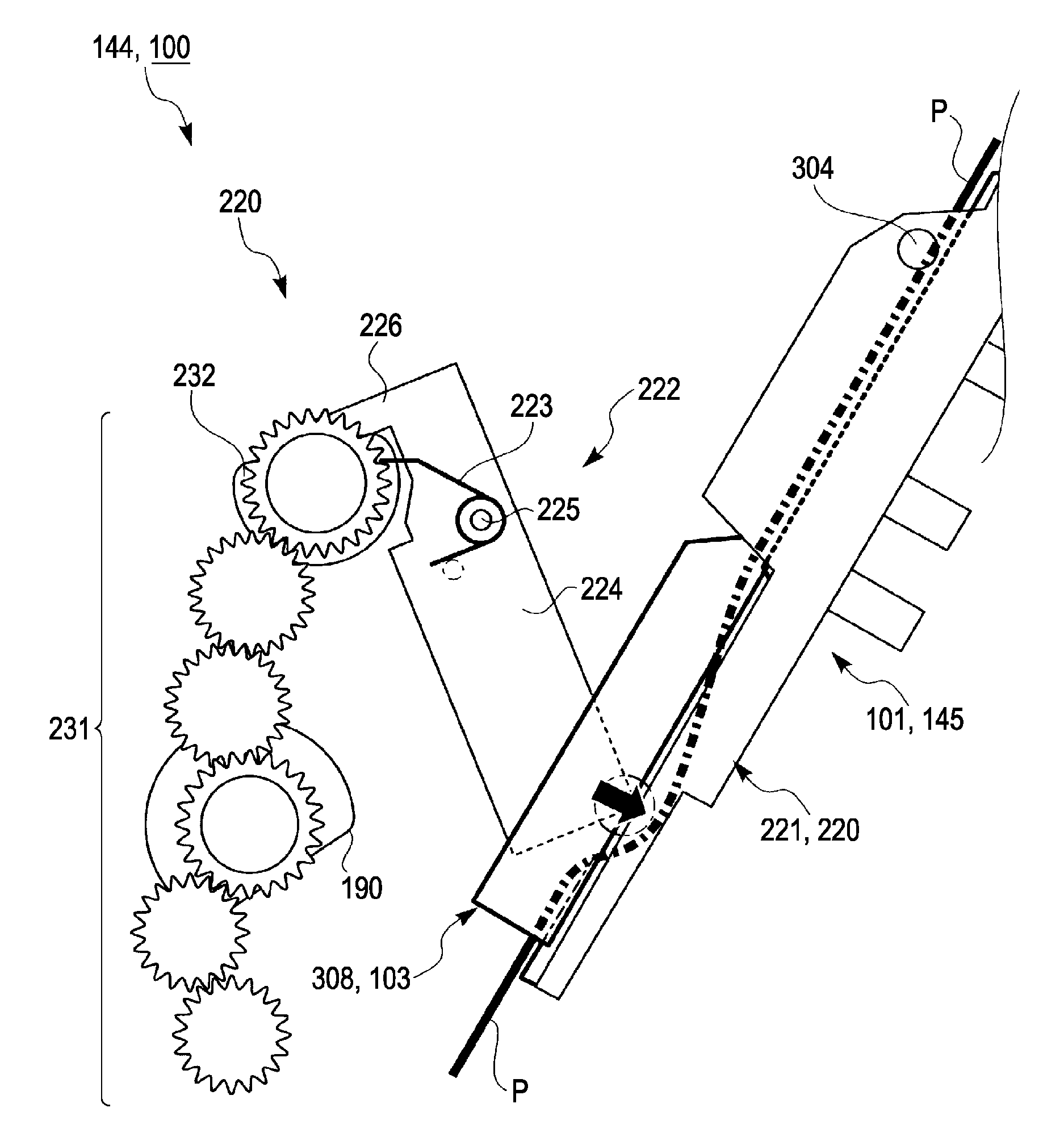
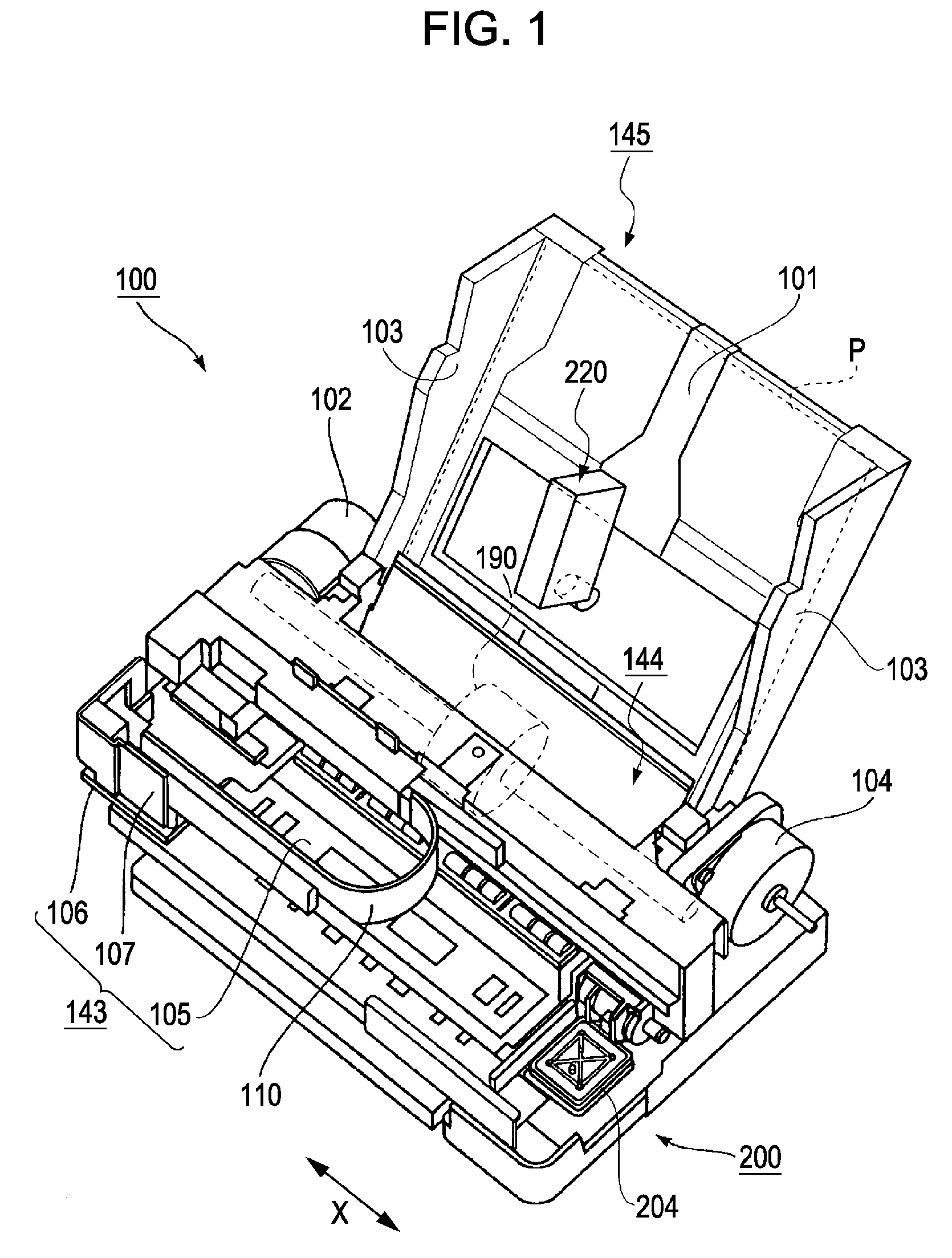
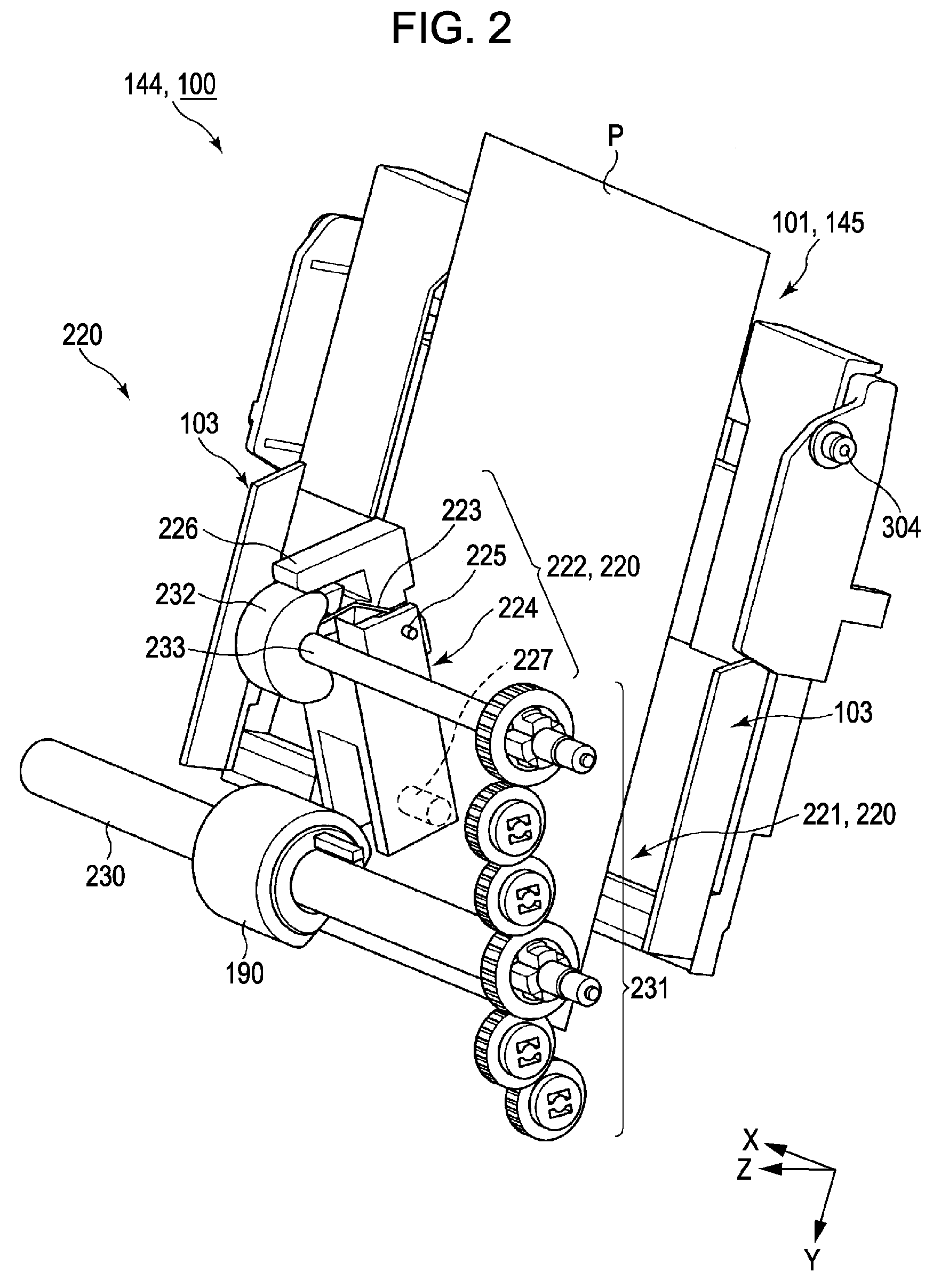
[0048]FIG. 1 is an overall perspective view illustrating a simple overview of a recording apparatus which is an example of a liquid ejection apparatus according to the invention.

[0049]Here, the term “liquid ejection apparatus” is not limited to an ink jet recording apparatus which performs a recording on a recording object by ejecting ink to the recording object, such as recording paper, from a recording head serving as a liquid ejection head and a recording apparatus, such as copier and facsimile, but is used to mean a structure including an apparatus which ejects liquid having a specific use instead of ink to an ejection object corresponding to the recording object from a liquid ejection head corresponding to the recording head and therefore attach the liquid to the ejection object.

[0050]Further, in addition to the recording head, examples of the liquid ejection head inclu...


PUM

PropertyMeasurementUnit
movementaaaaaaaaaa
widthaaaaaaaaaa
stiffnessaaaaaaaaaa

Abstract

A feeding device includes a mounting portion which mounts media thereon, a feeding roller which feeds the mounted media, an edge-guide which moves in a widthwise direction of the mounted media which traverses a feeding direction of the mounted media and aligns both sides of the mounted media, and a curve-imparting portion which imparts a curve to the mounted media in a direction which intersects a moving direction of the edge-guide.

Description

BACKGROUND[0001]1. Technical Field[0002]The present invention relates to a feeding device having a mounting portion which mounts media thereon, a feeding roller which feeds the mounted media, and an edge-guide which moves in a widthwise direction of the media which traverses a feeding direction of the mounted media and aligns both sides of the mounted media, and a recording apparatus having the feeding device. In this specification, examples of the recording apparatus include an ink jet printer, a wire dot printer, a laser printer, a line printer, a copier, a facsimile, etc.[0003]2. Related Art[0004]In the past, as disclosed in JP-A-2002-128286, a recording apparatus included a feeding roller which feeds paper and a hopper which can approach and depart from the feeding roller and on which the paper is mounted. A pair of edge-guides for guiding the paper in the widthwise direction of the paper is disposed in the hopper in a manner such that the edge-guides slide in the widthwise dire...

Claims


Application Information

Patent Timeline
Patent Type & Authority Patents(United States)
IPC IPC(8): B65H1/00
CPCB65H1/00B65H3/0661B65H9/101B65H2301/363B65H2801/06B65H2301/51212B65H2220/15
Inventor KOYANAGI, NORIYUKI
Owner SEIKO EPSON CORP
Why Eureka
Try Eureka