Method for manufacturing a syringe

a manufacturing method and syringe technology, applied in the field of pharmaceuticals, can solve the problems of least expensive loss, hazard to medical personnel, and the inability to equip “conventional” syringes with a corresponding backstop, and achieve the effect of less complicated and less expensiv

Inactive Publication Date: 2011-05-31
SCHOTT AG
View PDF24 Cites 4 Cited by
  • Summary
  • Abstract
  • Description
  • Claims
  • Application Information

AI Technical Summary

Benefits of technology

[0010]In vie of the above, it is an object of the present invention to provide a method for manufacturing a syringe with a backstop in a less complicated and less expensive manner.
[0011]It is another object of the present invention to provide a syringe having a backstop which is configured such that the syringe can be manufactured in a less complicated and less expensive manner.
[0012]It is yet another object of the present invention to provide an assembly component for manufacturing a syringe with a backstop in a less complicated and less expensive manner

Problems solved by technology

In addition, a syringe having a backstop is particularly suitable for very expensive and / or highly toxic medicaments, for example anti-cancer agents, because, if the plunger stopper were inadvertently pulled out, the medicament contained in the syringe could escape and thus pose a hazard to the medical personnel or would at least represent an expensive loss.
However, compared to syringes without a backstop, many of the known solutions require changes and / or additions to be made to the syringe barrel and / or to the plunger rod.
This means that “conventional” syringes cannot be equipped with a corresponding backstop.
As a result of this, these “special makes” are considerably more expensive than conventional syringes without a backstop.
The additional assembly step, also deviating from the other movements, entails added costs going beyond the simple material costs for the backstop.

Method used


Image

  • Method for manufacturing a syringe
  • Method for manufacturing a syringe
  • Method for manufacturing a syringe

Examples


Embodiment Construction

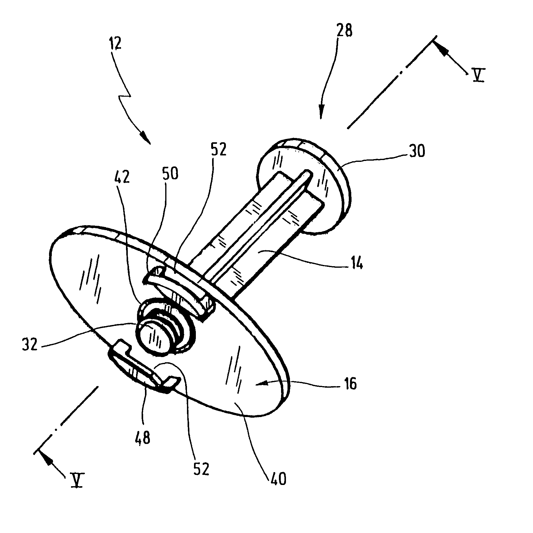
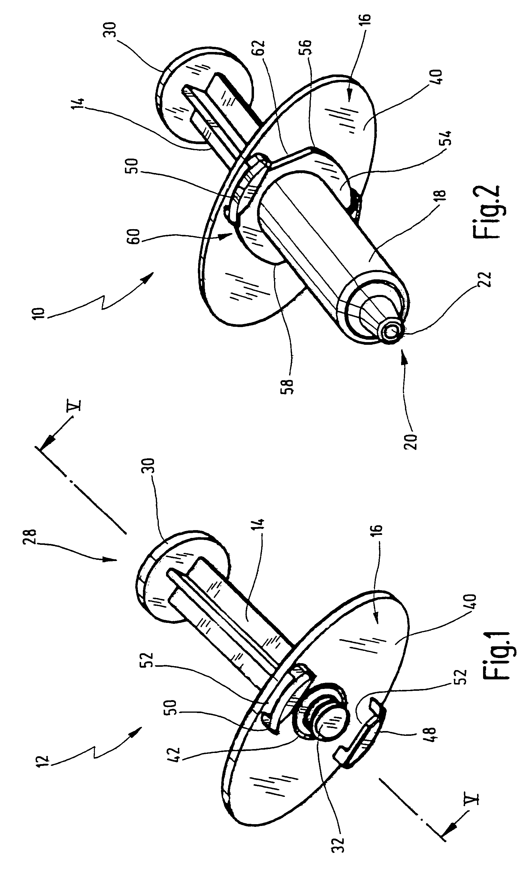
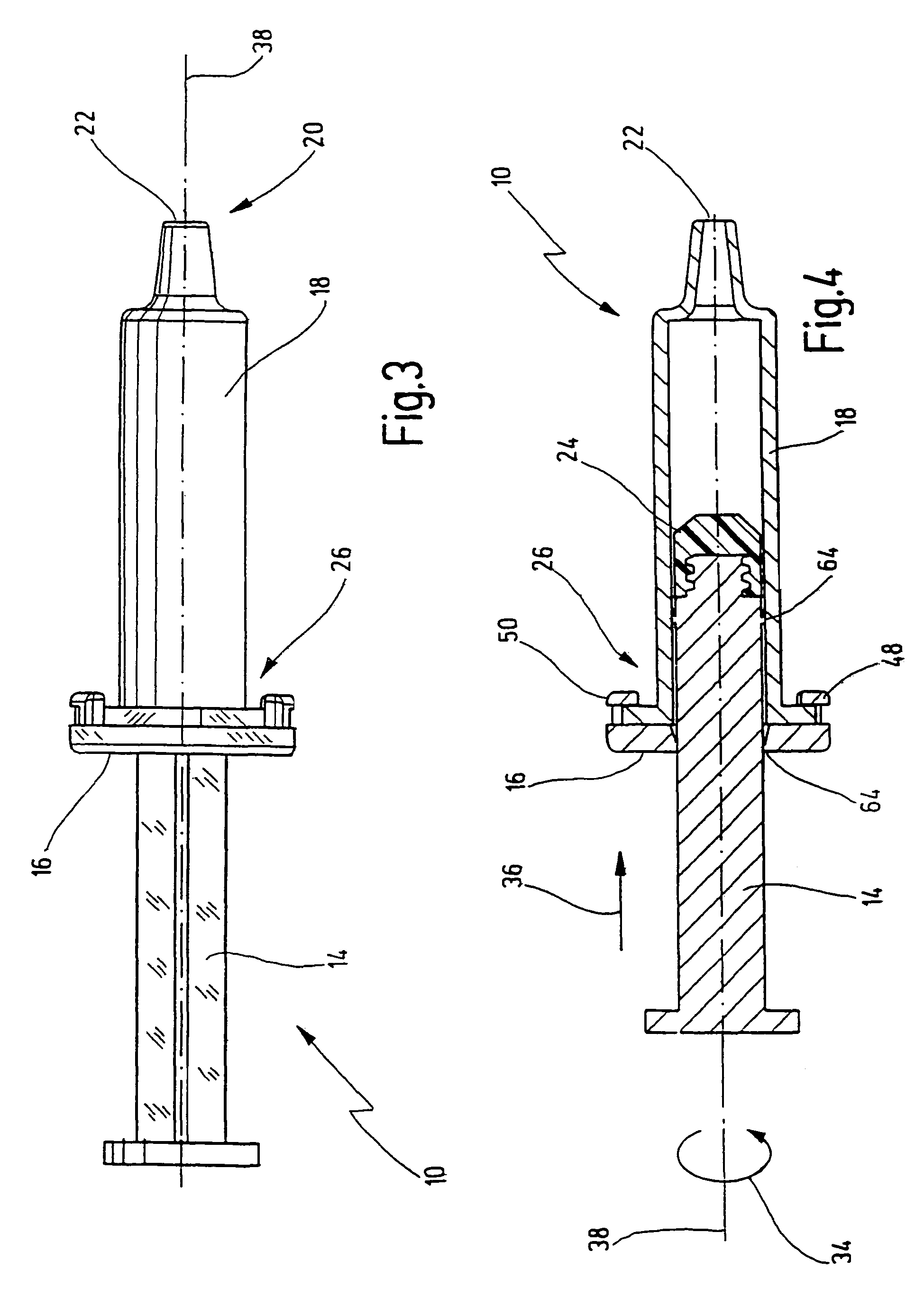
[0045]In FIGS. 1 to 4, a syringe manufactured in accordance with the novel method is designated in its entirety by reference number 10.

[0046]The syringe 10 is manufactured using an assembly component 12 which includes the subsequent plunger rod 14 and the subsequent backstop 16. Before final assembly of the syringe 12, plunger rod 14 and backstop 16 are materially connected to form the assembly component shown in FIG. 1.

[0047]Reference number 18 designates a syringe barrel which, in a manner known per se, has an opening 22 at its distal end 20. A cannula can be secured to the opening 22. Before its final assembly, the syringe 10 is preferably filled with a medicament (not shown here) and then closed with a plunger stopper 24 (FIG. 4) at the proximal end 26. This is usually done under sterile conditions by the pharmaceutical manufacturer of the medicament. For the sake of completeness, it should however be noted that the present invention is not limited solely to syringes for these a...


PUM


Abstract

A syringe has a syringe barrel into which a plunger stopper is inserted during a manufacturing process. A plunger rod is connected to the plunger stopper, and a backstop for preventing inadvertent removal of the plunger stopper from the syringe barrel is arranged at the proximal end of the syringe barrel. The backstop and the plunger rod are configured to form a combined assembly component which is adapted to be mounted to the syringe barrel in a combined manufacturing step. After mounting the combined assembly component to the syringe barrel, the backstop and the plunger rod are separated to allow conventional use of the syringe.

Description

[0001]The present invention relates to a method for manufacturing a syringe, in particular a syringe for medical applications, and further to a syringe manufactured in accordance with this method, and to a combined assembly component used in the manufacturing process according to the present invention. More specifically, the present invention relates to a syringe having a backstop arranged at the proximal end of a syringe barrel, and to a process of manufacturing the same.BACKGROUND OF THE INVENTION[0002]In the pharmaceutical industry, there are a number of medicaments which are already filled into medical syringes at the place of manufacture. The pharmaceutical manufacturer fills the medicament, under sterile conditions, into a sterile syringe barrel which is closed off at the distal end with a sealing cap. The syringe barrel is then closed off at the proximal end with a sterile plunger stopper, frequently made of rubber-elastic material. Thereafter, the plunger rod of the syringe ...

Claims


Application Information

Patent Timeline
Patent Type & Authority Patents(United States)
IPC IPC(8): A61M5/315A61M5/31A61M5/50
CPCA61M5/3135A61M5/31505A61M2005/3139A61M2005/3121A61M5/5086
Inventor WOLBRING, PETERMOSIMANN, RALPHDIEM, HANSPETER
Owner SCHOTT AG
Why Eureka
Try Eureka