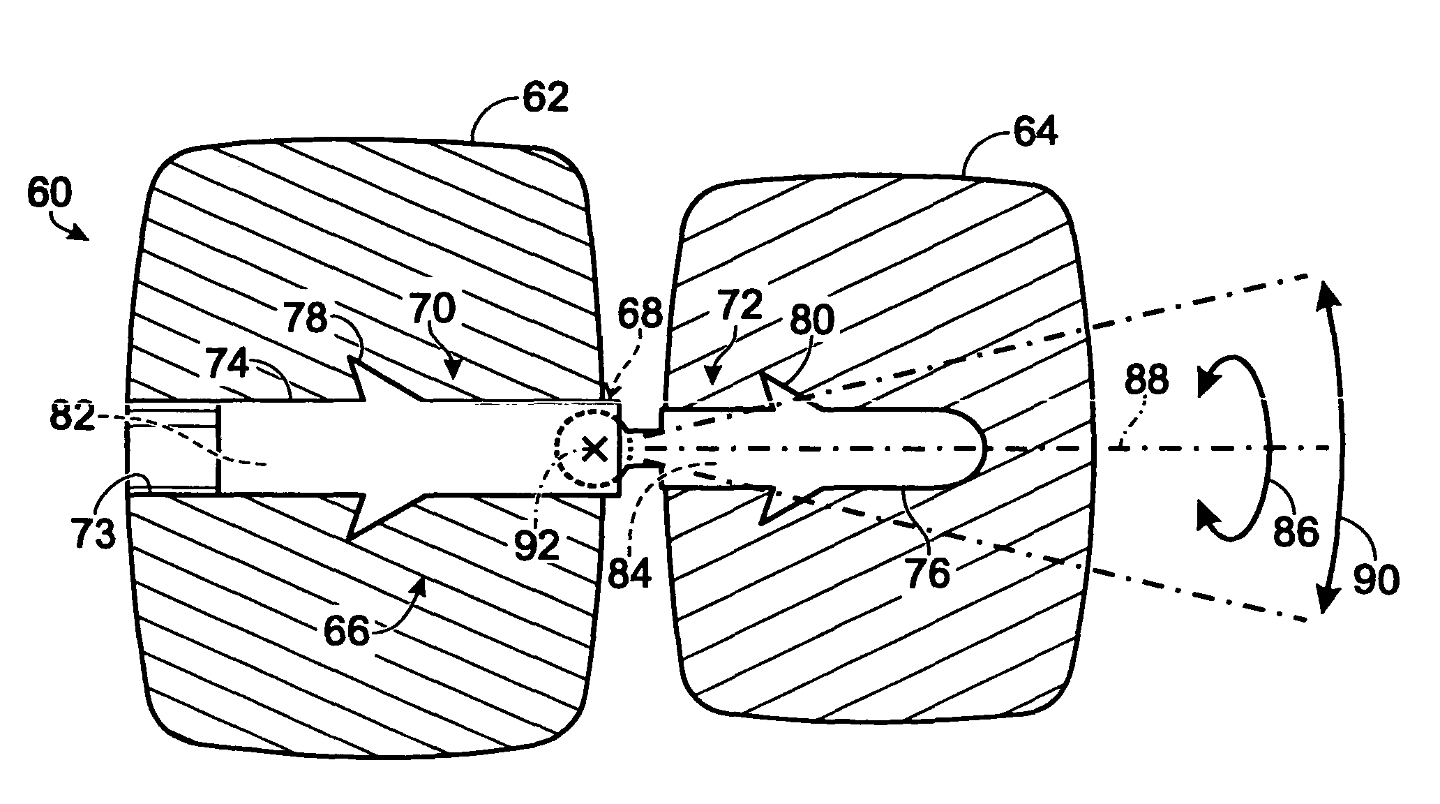
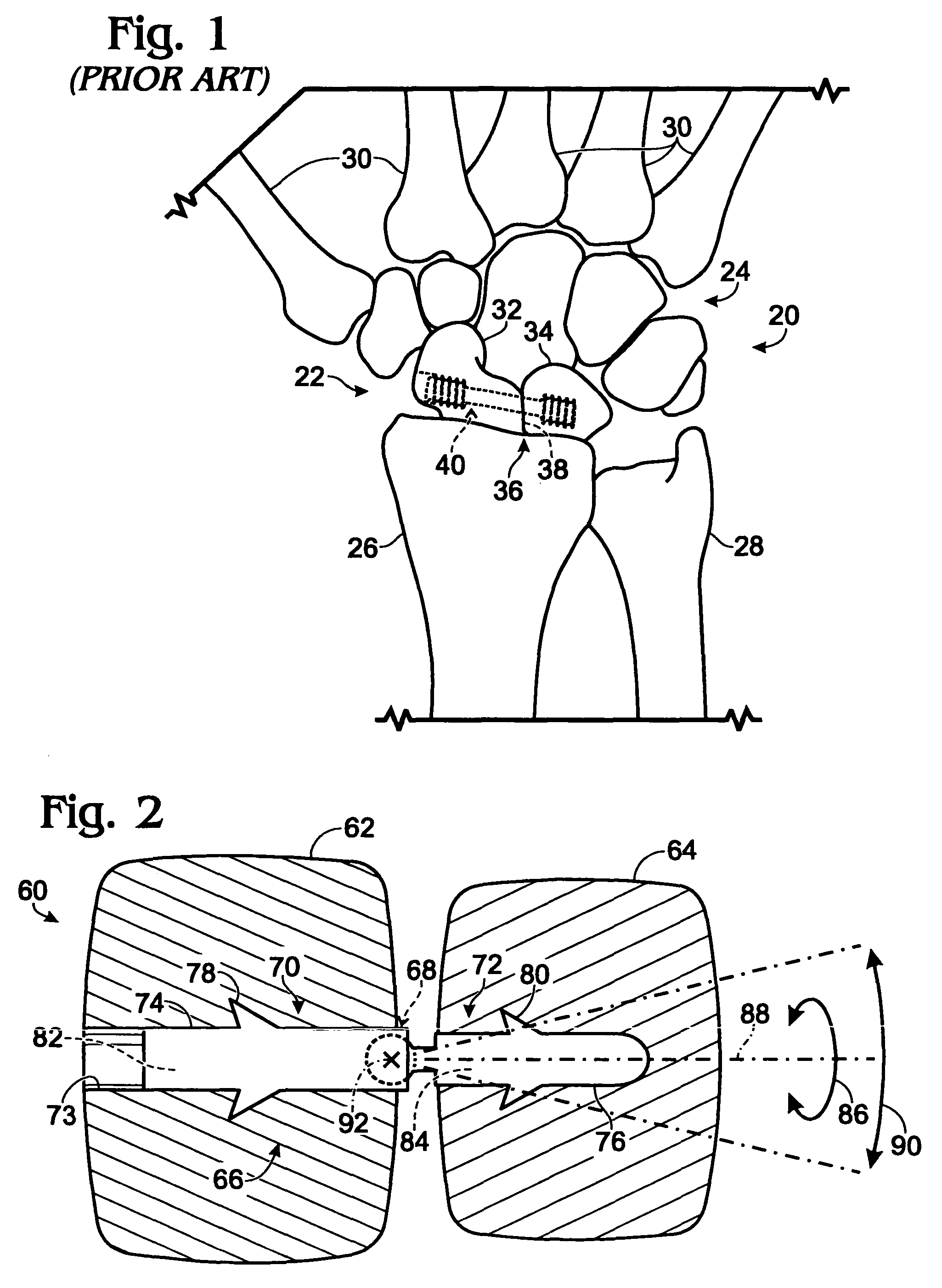
Bone connector with pivotable joint
a bone connector and pivotable technology, applied in the field of bone connectors with pivotable joints, can solve the problems of long-term loss of wrist function, scar tissue formation, and arthritic degeneration of the radiocarpal join
- Summary
- Abstract
- Description
- Claims
- Application Information
AI Technical Summary
Benefits of technology
Problems solved by technology
Method used
Image
Examples
example 1
Jointed Bone Screw 1
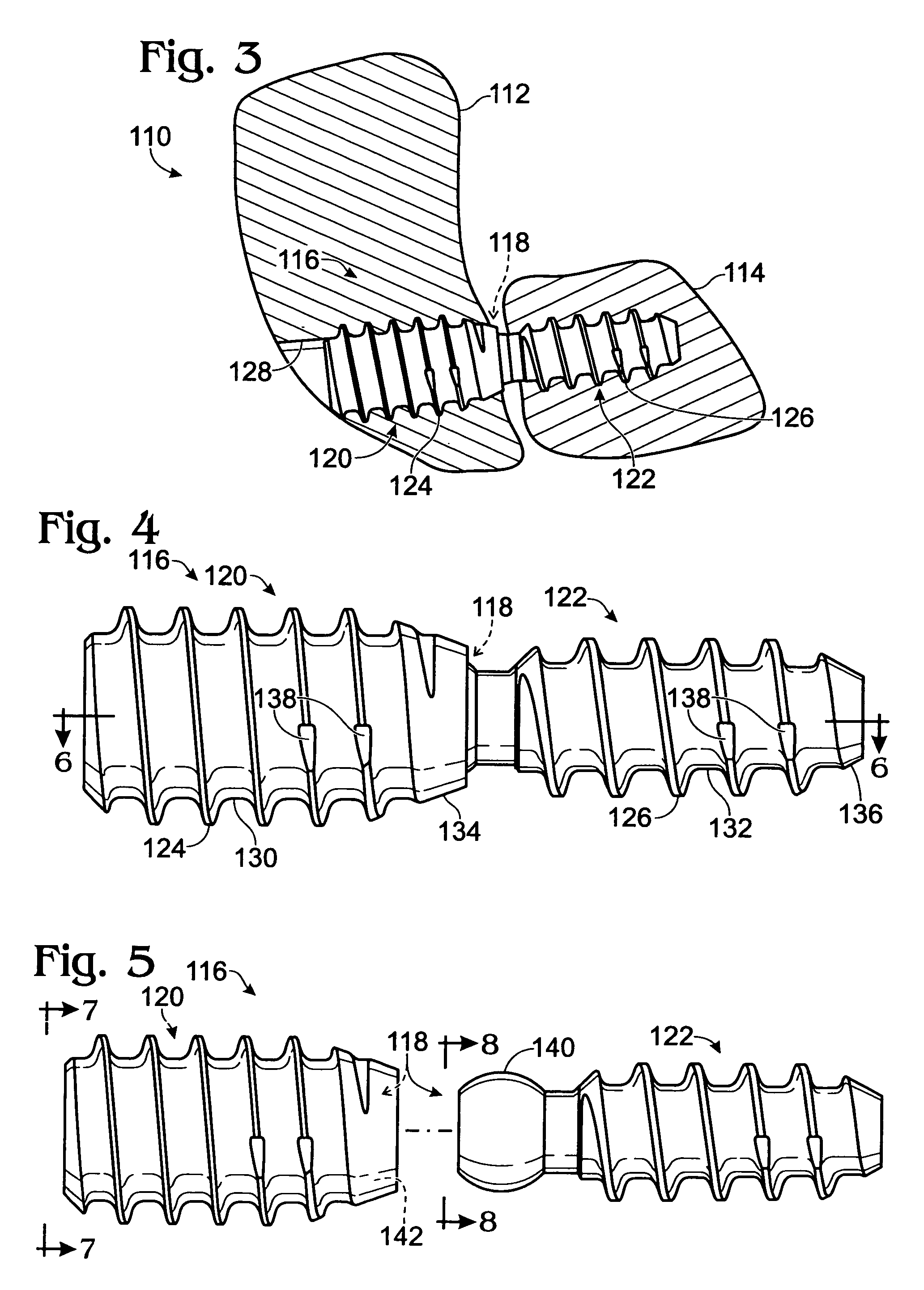
[0059]This example describes selected aspects of jointed bone screw 116; see FIGS. 4-8. Additional aspects of bone screw 116 are described above in relation to FIG. 3.
[0060]FIG. 4 shows bone screw 116 in an assembled configuration with pivotable joint 118 directly connecting trailing screw element 120 to leading screw element 122. The screw elements may have any suitable size and shape. In some examples, the screw elements may have about the same diameter. Alternatively, the leading screw element may be lesser in diameter than the trailing screw element, such as having a lesser average diameter, a lesser maximum diameter, and / or a lesser median diameter than the trailing screw element. Each screw element may have a body 130, 132 on which respective external threads 124, 126 may be formed. Each body may be generally cylindrical, as shown here, and / or may taper in a linear or nonlinear fashion, such as to create a body that is partially or completely frustoconical....
example 2
Jointed Bone Screw 2
[0064]This example describes another exemplary bone screw with a pivotable joint; see FIGS. 9-11.
[0065]FIGS. 9-11 show respective exploded, assembled, and sectional views of an exemplary bone screw 180 with a pivotable joint 182 that directly connects screw elements 184, 186. The pivotable joint of the bone screw may be formed by a protruding portion 188, such as a widened end region or head, of one of the screw elements received in a joint cavity 190 of the other screw element. The protruding portion and the joint cavity may have any suitable shapes that permit mating and relative pivotal motion. In the present illustration, the trailing screw element 184 has a semispherical head and the leading screw element defines a complementary semispherical socket disposed near the trailing end of the screw element. One or both screw elements may include a spacer or neck region 192. The spacer region may be nonthreaded and configured to space the head (or socket) from a th...
example 3
Jointed Bone Screw 3
[0073]This example describes yet another exemplary bone screw 240 with a pivotable joint; see FIG. 12.
[0074]Bone screw 240 may include a plurality of screw elements 242, 244 coupled via a ball-and-socket joint 246. A female portion or socket 248 of joint 246 may be provided by trailing screw element 242. A male portion or ball 250 of joint 246 may be provided by leading screw element 244.
[0075]The proximal and distal screw members, when aligned, cooperatively may form a driver engagement structure 252 for receiving a driver. In some embodiments, the driver engagement structure may be formed by portions forming a hole, such as a hexagonal socket, with a constant cross section. The trailing portion of the hexagonal socket may extend axially at least substantially or completely from the trailing end of the trailing screw element to joint socket 248. The leading portion of the hexagonal socket may extend any suitable distance along leading screw element 244. In some ...
PUM
 Abstract
Description
Claims
Application Information
 - R&D
- Intellectual Property
- Life Sciences
- Materials
- Tech Scout
- Unparalleled Data Quality
- Higher Quality Content
- 60% Fewer Hallucinations
Browse by: Latest US Patents, China's latest patents, Technical Efficacy Thesaurus, Application Domain, Technology Topic, Popular Technical Reports.
© 2025 PatSnap. All rights reserved.Legal|Privacy policy|Modern Slavery Act Transparency Statement|Sitemap|About US| Contact US: help@patsnap.com


