
Stabilizing oscillation amplitude of torsion oscillator at predetermined frequency

a torsion oscillator and stability technology, applied in the field of control of torsion oscillators, can solve the problems of increasing system complexity and cost, time-consuming and expensive complex processes, etc., and achieves the effects of reducing manufacturing costs, simplifying the control method of torsion oscillators, and saving the computation time of resonance frequency

Active Publication Date: 2011-05-31
AURISE INVESTMENT CO LTD
View PDF3 Cites 0 Cited by
  • Summary
  • Abstract
  • Description
  • Claims
  • Application Information

AI Technical Summary

Benefits of technology

[0007]One objective of the present invention is to provide a method of controlling a torsion oscillator to stabilize the oscillation amplitude of the torsion oscillator at a predetermined frequency with simplified control method.
[0008]Another objective of the present invention is to provide a method of controlling a torsion oscillator to stabilize the oscillation amplitude of the torsion oscillator at a predetermined frequency for saving the computation time by eliminating the needs of finding resonance frequency of the torsion oscillator.
[0009]Still another objective of the present invention is to provide a method of controlling a torsion oscillator to stabilize the oscillation amplitude of the torsion oscillator at a predetermined frequency for decreasing the manufacturing cost of the image systems.

Problems solved by technology

In addition, the resonance frequency may also depend on the drive energy level; therefore, the procedures of determining resonance frequency and maintaining oscillation amplitude by altering drive energy level are coupled and complex processes which are time consuming and expensive.
Therefore, the drive motor speeds of the OPC drum and of the paper feeding mechanism, and the timing of laser modulation need to be controlled precisely that leads to increase of system complexity and cost.

Method used


Image

  • Stabilizing oscillation amplitude of torsion oscillator at predetermined frequency
  • Stabilizing oscillation amplitude of torsion oscillator at predetermined frequency
  • Stabilizing oscillation amplitude of torsion oscillator at predetermined frequency

Examples


first embodiment

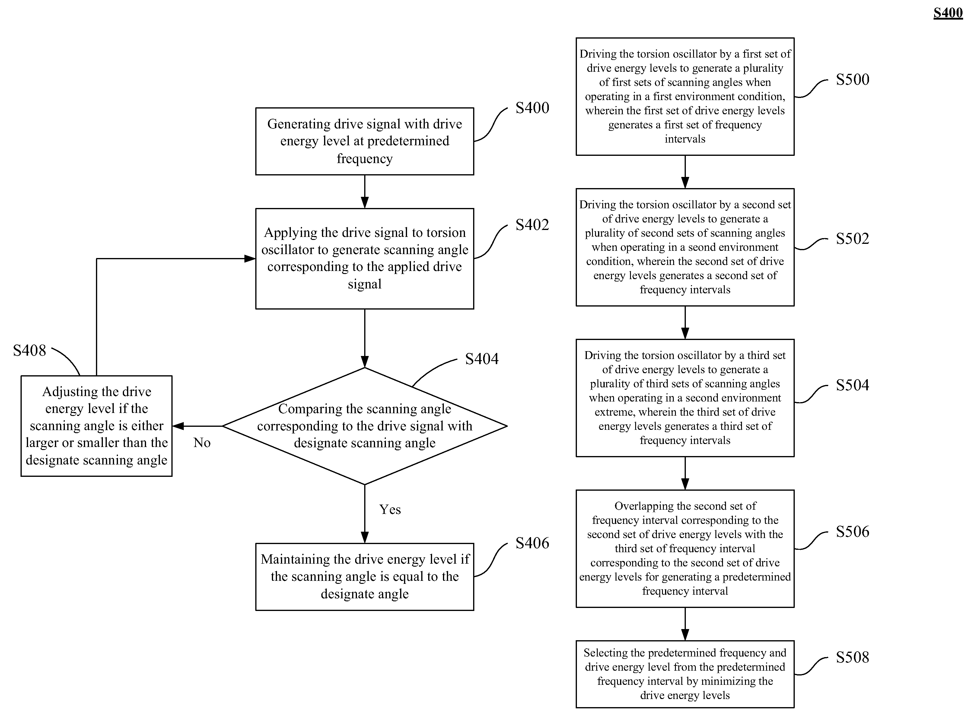
[0039]The predetermined frequency and the corresponding drive energy level in step S400 are pre-selected based on results of characterization tests of the torsion oscillator under operating environment extremes. FIG. 5A is a flow chart of defining the predetermined frequency according to the present invention. In step S500, when the torsion oscillator 304 is operated in a first environment condition T1, the first set of drive energy levels V11 and V12 drive the torsion oscillator 304 to generate a plurality of first sets of scanning angles. Each of the first sets of scanning angles corresponds to the first set of drive energy levels V11 and V12, and thus generates the first set of frequency response curves S11 and S12 as shown in FIG. 5B. The drive energy level V11 is preferably greater than the drive energy level V12 and generates larger scanning angle of the torsion oscillator 304. The first set of drive energy levels V11 and V12 corresponds to the first set of frequency response ...

second embodiment

[0046]FIG. 6A is a flow chart for determining the predetermined frequency according to the present invention for torsion oscillator 304 exhibiting unsymmetrical or nonlinear frequency response. The nonlinear frequency responses of the torsion oscillator 304 are shown in FIG. 6B and it is to be noted that the frequency response curve is not symmetrical to its resonance frequency. For the case that the torsion oscillator 304 is driven by energy level V41 under an environment condition T4, the scanning angle of the torsion oscillator 304 increases as the drive signal frequency, higher than the frequency fR4 decreases and the scanning angle reaches the maximum when the frequency equals fR4, defined as the resonance frequency. The scanning angle drops rapidly if the drive frequency continues to decrease below the resonance frequency fR4. The region below the resonance frequency fR4 is an unstable region since the scanning angle will experience a drastic change with slight change of the d...


PUM


Abstract

A control method of stabilizing the oscillation amplitude of a torsion oscillator is described. The method includes the steps of: driving a torsion oscillator at a predetermined frequency with a drive energy level by a control module to generate a scanning angle of the incident light beam, wherein the drive energy level is associated with the predetermined frequency; comparing the scanning angle corresponding to the drive energy level with a designate scanning angle by the control module; and adjusting the drive energy level based on the comparison result until the scanning angle of the torsion oscillator is equal to the designate scanning angle.

Description

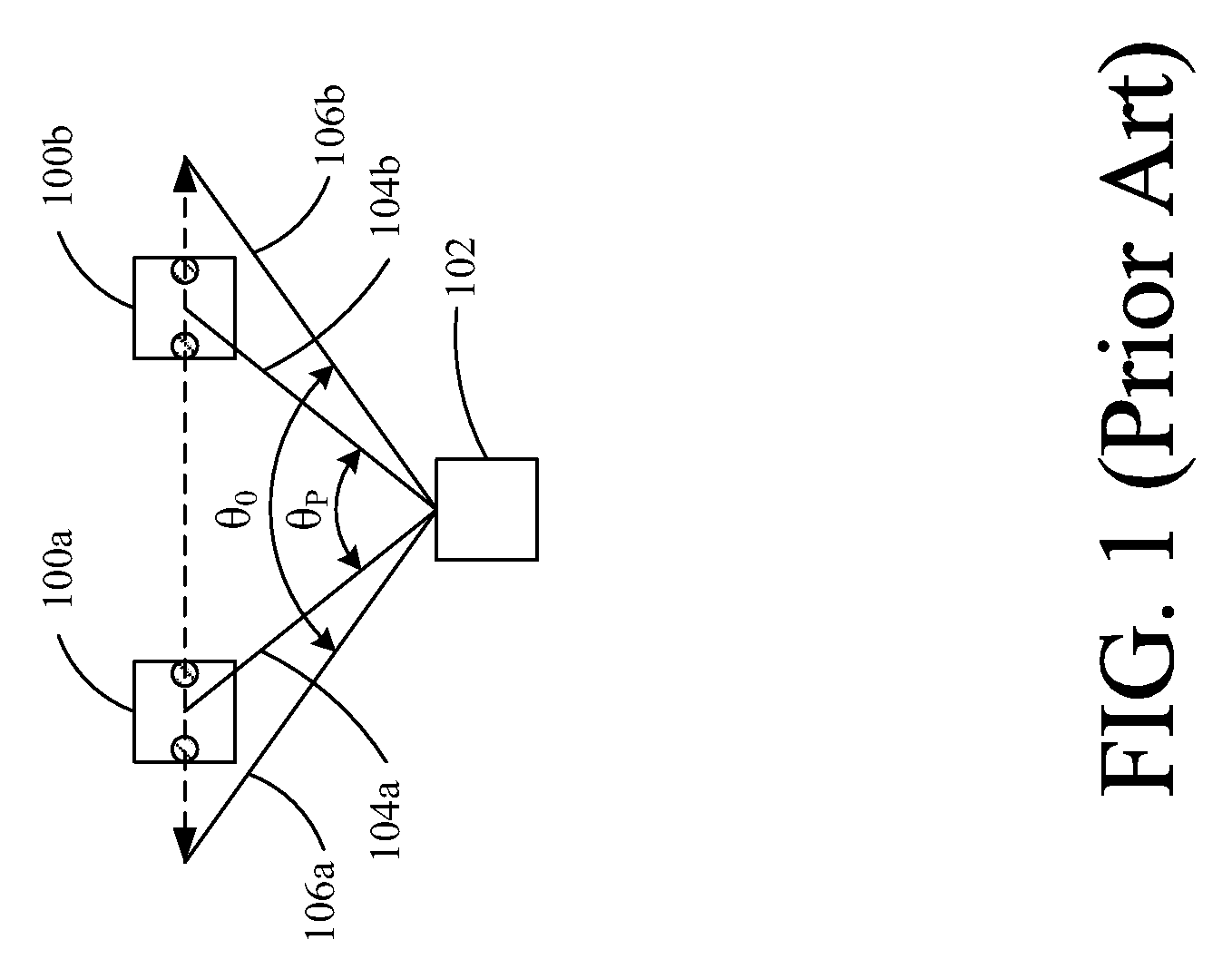
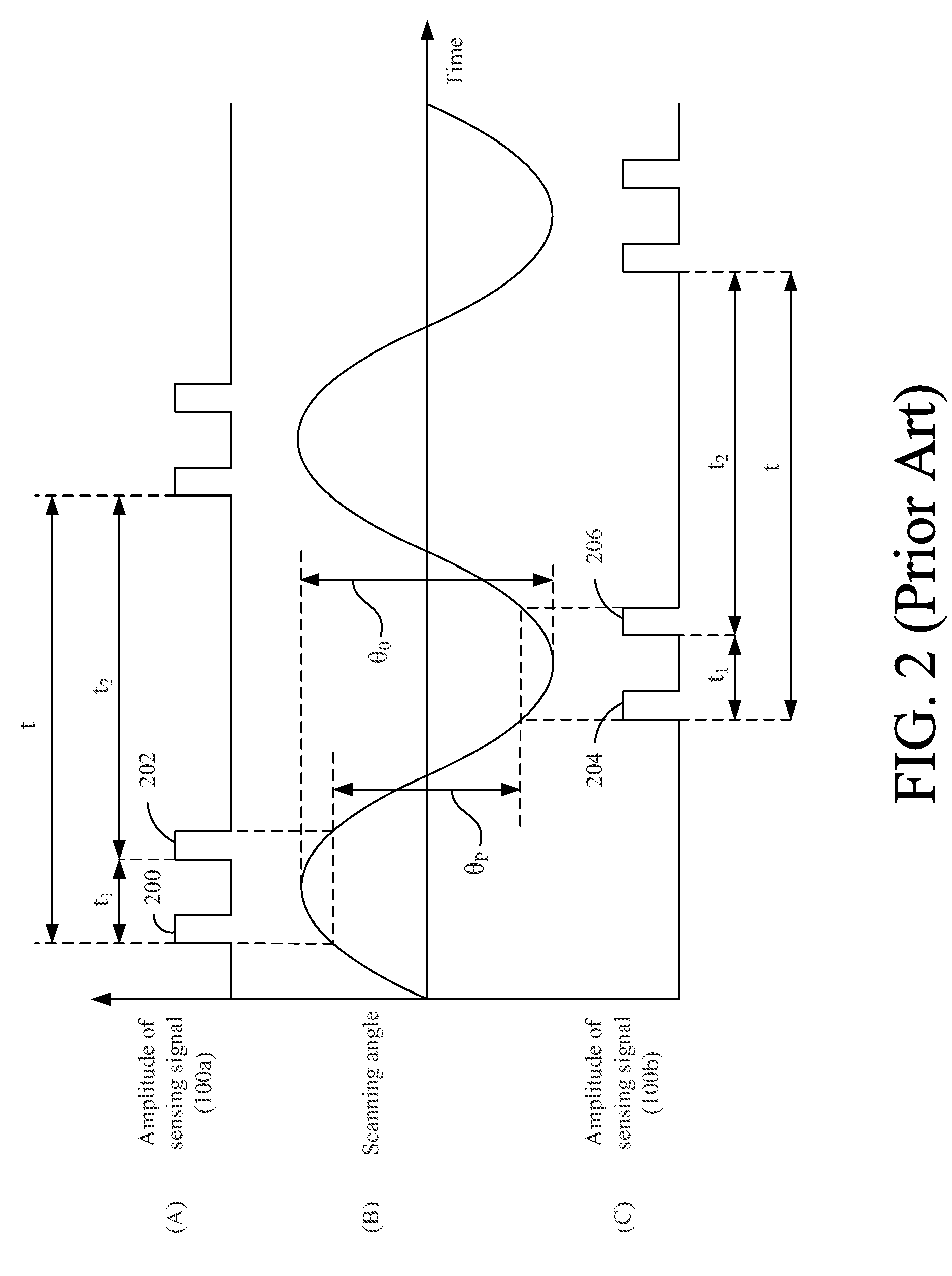
FIELD OF THE INVENTION[0001]The present invention relates to a method of controlling a torsion oscillator, and more particularly relates to a method of controlling a torsion oscillator to stabilize its oscillation amplitude at a predetermined frequency.BACKGROUND OF THE INVENTION[0002]Torsion oscillators are widely used in laser printers, copiers, fax machines, bar code scanners, laser scanning projectors, laser radars and laser scanning sensors etc. The reflective mirror of the torsion oscillator swings back and forth periodically and deflects the incident light beam to form a scanning span or a scanning angle. The torsion oscillator can be driven by various principles, such as electromagnetic force, electrostatic force, or piezoelectric force. The span or angle of the oscillation can be controlled by adjusting the drive energy input to the torsion oscillator. In case of electromagnetic force, the torsion oscillator can be actuated by the Lorentz's force which can be generated by a...

Claims


Application Information

Patent Timeline
Patent Type & Authority Patents(United States)
IPC IPC(8): G02B26/08
CPCG02B26/105
Inventor HUNG, CHANG-LI
Owner AURISE INVESTMENT CO LTD
Learn More