Parallel inverter current control method adopting voltage differential compensation

A technology using voltage and current control, applied in the direction of converting AC power input to DC power output, electrical components, output power conversion devices, etc. The reduction of wave current suppression ability and the reduction of grid-connected inverter power generation efficiency, etc., achieve the effects of good output current waveform, small filter damping resistance loss, and simple and feasible control method

Inactive Publication Date: 2009-10-07
ZHEJIANG UNIV
View PDF0 Cites 34 Cited by
  • Summary
  • Abstract
  • Description
  • Claims
  • Application Information

AI Technical Summary

Problems solved by technology

Because the filter of the LCL structure makes the control object a third-order system, if the filter is not damped or the damping is insufficient, there will be a large gain peak near the corner frequency of the filter. In order to ensure the stability of the system, the gain of the proportional-integral regulator is limited. , the value is small, so that the open-loop gain of the system in the low frequency band is small, which limits the ability of the system to suppress the output current steady-state error and harmonics; if the filter is added with sufficient damping, the current flowing through the damping resistor, Especially the high-frequency ripple current will generate a large power loss on the damping resistor, which not only reduces the power generation efficiency of the grid-connected inverter, but also causes heat dissipation problems, and this method will also cause the filter to invert The ripple current suppression ability caused by the high-frequency switching of the device is reduced, and the switching ripple current in the grid current is increased.

Method used


Image

  • Parallel inverter current control method adopting voltage differential compensation
  • Parallel inverter current control method adopting voltage differential compensation
  • Parallel inverter current control method adopting voltage differential compensation

Examples


Embodiment Construction

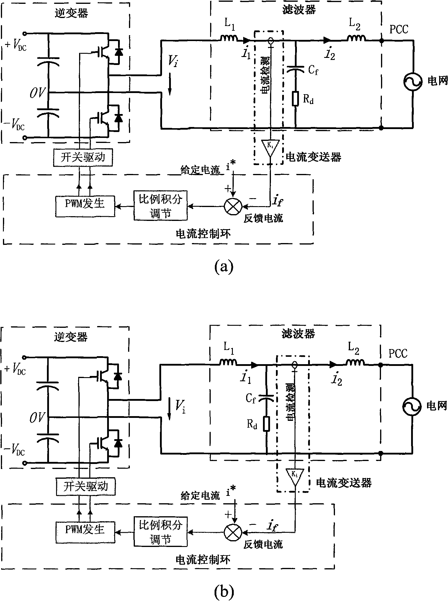
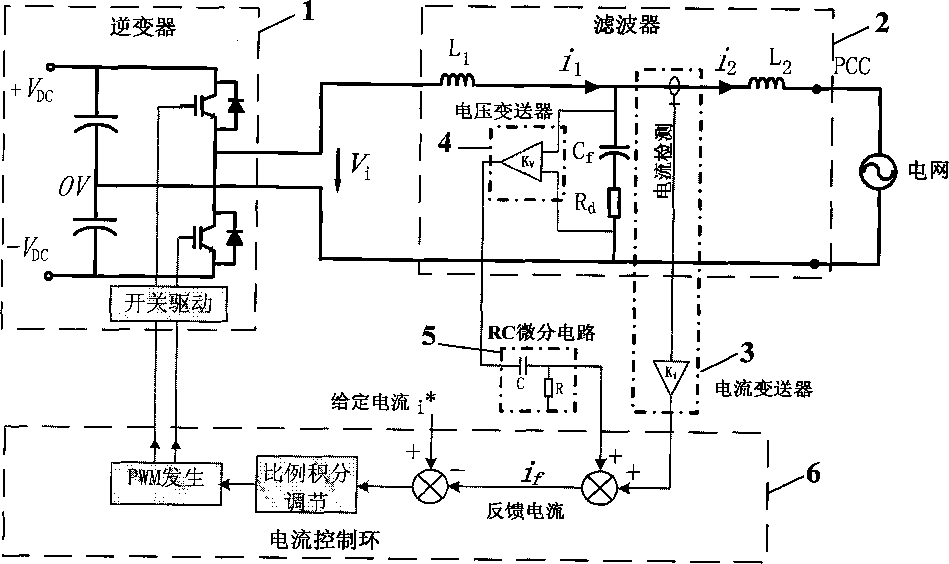
[0013] figure 2 Shown is the grid-connected inverter circuit that adopts the method of the present invention, including the pulse width modulation control inverter 1 based on high-frequency switches (in the illustration, the single-phase inverter is a voltage source type half-bridge, using IGBT as the power switch), LCL filter 2 for inverter grid connection, current transducer 3 for current detection, voltage transducer 4 for voltage detection and RC differential circuit 5, for inverter grid connection The current control loop 6 including current error calculation, error signal proportional integral regulator and pulse width modulation (PWM) generator running current feedback control, wherein the LCL filter is formed by the inverter side inductance L 1 , bypass capacitor C f and a series damping resistor R d and grid side inductance L 2 composed of a T-shaped circuit,

[0014] The current control method of the grid-connected inverter is: use the current transmitter to det...


PUM


Abstract

The invention discloses a parallel inverter current control method adopting voltage differential compensation, which comprises: adopting a LCL wave filter composed by capacitor and damping resistor in series connection to connect with a PWM inverter and power network; adopting a current transmitter to detect the current in the inductor on the power network side of the wave filter and obtain power network current signal; adopting a piezoelectric sender to detect the capacitor branch voltage of the wave filter and obtain current compensation signal by the RC differential circuit; combining the two signals into one signal as a feedback signal for current control of the inverter; comparing with the control given signal of the power network current to obtain error signal; and adjusting and controlling the output of the PWM inverter by proportional integration, wherein, the transformation ratio of the piezoelectric sender and the RC differential time constant are determined by the LCL wave filter parameter. Compared with conventional current feedback control methods, the invention can reduce the damping resistance of the LCL wave filter, thereby reduce the loss caused by damping resistance and improves the ability of the wave filter for inhibiting the ripple current of the inversion switch.

Description

technical field [0001] The invention relates to a control method for a grid-connected inverter, in particular to a current control method for a grid-connected inverter using voltage differential compensation. Background technique [0002] The inverter power supply with grid-connected power generation function, its circuit is as follows figure 1 As shown in (a) and (b), it usually includes PWM (pulse width modulation) control inverter based on high-frequency switching, LCL low-pass filter for inverter grid-connected operation, and electrorheological for current detection The inverter and the current control loop including the current error calculation and the error signal proportional integral regulator for the grid-connected operation of the inverter, the inverter controls the output current during the grid-connected operation to ensure that the current is a strict sine wave parallel It has a high power factor of power generation. Most of the traditional current control me...

Claims


Application Information

Patent Timeline
Patent Type & Authority Applications(China)
IPC IPC(8): H02M7/5395H02M1/12
Inventor 沈国桥徐德鸿
Owner ZHEJIANG UNIV
Why Eureka
Try Eureka