
Heating apparatus, fixing apparatus, and image forming apparatus which charges an auxiliary power unit to less than a maximum value in a standby status

a technology of fixing apparatus and heating apparatus, which is applied in the direction of electrographic process apparatus, instruments, optics, etc., can solve the problems of excessive electric power supply, abnormal temperature rise of heating units, and decreased usability of such an image forming apparatus

Inactive Publication Date: 2011-05-31
RICOH KK
View PDF33 Cites 8 Cited by
  • Summary
  • Abstract
  • Description
  • Claims
  • Application Information

AI Technical Summary

Benefits of technology

The present invention provides an improved heating apparatus, fixing apparatus, and image forming apparatus that can prevent abnormal temperature rise and return time issues. The invention achieves this by controlling the electric power supply to the heating units and the auxiliary power unit, ensuring that the first maximum value of electric energy charged in the auxiliary power unit is less than the second maximum value. This prevents the abnormal rising of temperature upon repeating the feeding of a small number of pieces of paper and ensures improved images. Additionally, the invention provides a heating apparatus that can reduce the return time upon returning from the off mode.

Problems solved by technology

As a result, the image forming apparatus requires time to be enabled, so that the usability of such an image forming apparatus is decreased.
Thus, in the paper-feed status, excessive electric power is supplied to the heat generator from the auxiliary power unit.
Accordingly, when a small number of pieces of paper are fed repeatedly, using three pieces of paper at one time or using five pieces of paper at one time, for example, it is feared that abnormal temperature rising may be caused in the heating units by supplying excessive electric power to the heat generator from the auxiliary power unit.
Further, there has been a problem in that the heating units are excessively heated and abnormal temperature rising may be caused in the heating units upon repeating the feeding of a small number of pieces of paper if excessive electric power is charged in the auxiliary power unit in the standby status and than discharged from the auxiliary power unit to the heat generator in the paper-feed status.
Moreover, when repeating the feeding of a small number of pieces of paper, if the maximum electric energy charged in the auxiliary power unit in the standby status is limited to a relatively low level so as not to cause the abnormal rising of the temperature of the heating units and the apparatus is returned from the off mode with the maximum electric energy, it is difficult to raise the temperature of the heating units in a short time due to a shortage of electric power on this occasion.

Method used


Image

  • Heating apparatus, fixing apparatus, and image forming apparatus which charges an auxiliary power unit to less than a maximum value in a standby status
  • Heating apparatus, fixing apparatus, and image forming apparatus which charges an auxiliary power unit to less than a maximum value in a standby status
  • Heating apparatus, fixing apparatus, and image forming apparatus which charges an auxiliary power unit to less than a maximum value in a standby status

Examples


first embodiment

[0051]FIG. 6 shows an image forming apparatus having a fixing apparatus according to the present invention. In FIG. 6, numeral 41 designates a drum photoconductor as an example of an image carrier made of a rotator. On the periphery of the photoconductor 41, there are disposed an electrifying unit 42 made of an electrifying roller, a mirror 43 constituting a portion of an exposure unit, a developing unit 44 provided with a developing roller 44a, a transferring unit 48 for transferring a developed image to a piece of paper P used as a recording material, a cleaning unit 46 provided with a blade 46a in slidable contact with a circumferential surface of the photoconductor 41, and the like in order of a rotation direction indicated by an arrow in the figure. The photoconductor 41 is scanned and exposed between the electrifying unit 42 and the developing roller 44a by the exposure unit using an exposure light Lb via the mirror 43. A position of the photoconductor 41 where the exposure li...

second embodiment

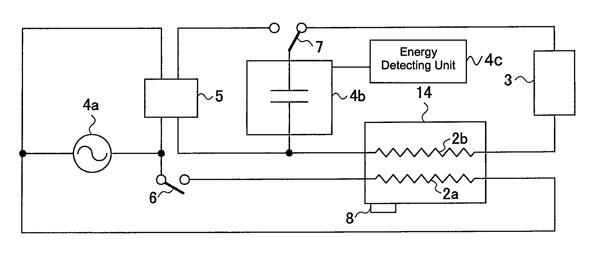
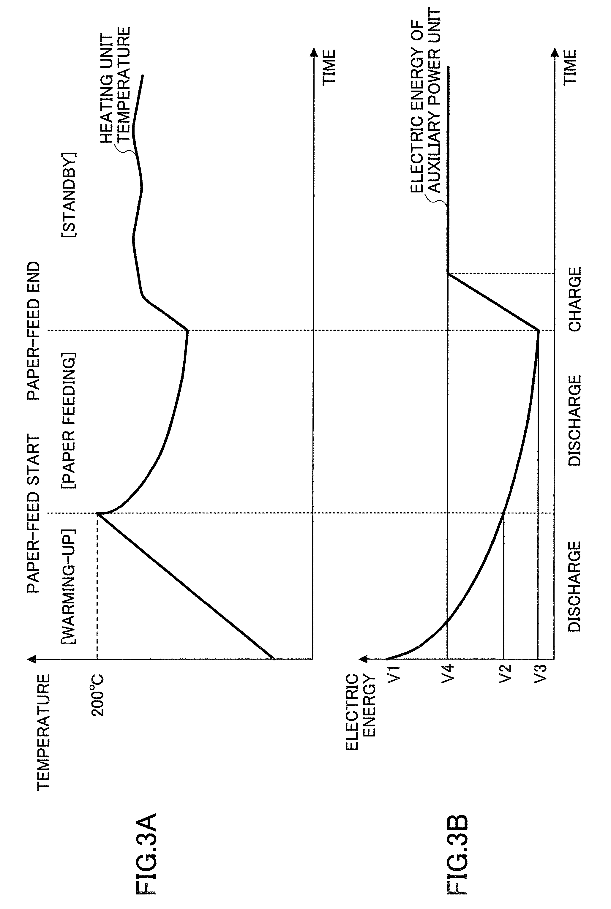
[0074]It is difficult to raise the temperature of the heating unit 14 in a short time due to a lack of electric energy when saving the maximum electric energy charged in the auxiliary power unit 4b in the standby status so as not to cause the abnormal rising of the temperature of the heating unit upon repeating the feeding of a small number of pieces of paper and then trying to return from the off mode to the temperature for enabling the heating unit 14 to perform fixing without changing the maximum electric energy. In view of this, when the electric power supply to the heat generator 2 is stopped (the off-mode), the auxiliary power unit 4b is charged to the maximum value V1 of electric energy that can be charged, so that it is possible to reduce return time when returning to the temperature for enabling the heating unit 14 to perform fixing.

[0075]FIG. 5 is a waveform diagram showing the temperature of the heating unit 14 and the electric energy in the auxiliary power unit 4b in a ...

third embodiment

[0077]In the third embodiment, the temperature of the heat generator 2 is controlled to be a set temperature or the set temperature ±10° C. by the control of main power source switch 6 of the first control unit, namely, 180° C., for example. In the warming-up status or the return status for returning from the off mode to the temperature for enabling the heating unit 14 to perform fixing, the temperature of the heat generator 2 is raised to 200° C., for example. When the temperature is lowered in the paper-feed status, the temperature is maintained to be a lower limit temperature for enabling fixing, namely, not less than 160° C., for example.

[0078]According to the third embodiment, when electric energy V5 not less than the electric energy V4 is charged in the auxiliary power unit 4b, the electric energy V4 being the first maximum value of electric energy charged in the auxiliary power unit 4b in the standby status, the charging of the auxiliary power unit 4b is not performed until t...


PUM


Abstract

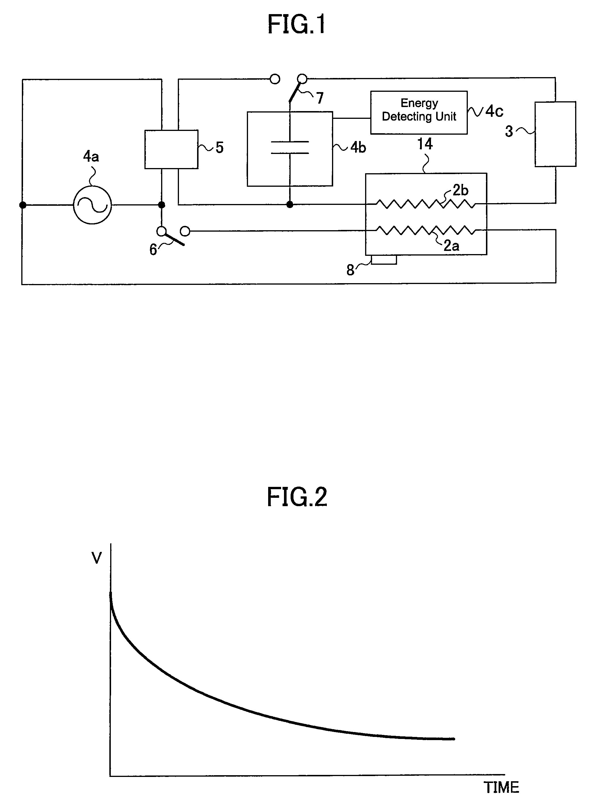
A disclosed heating apparatus comprises: a heat generator for receiving electric power supply from a main power source and an auxiliary power unit and generating heat; a heating unit heated by the heat generator; a charging unit for charging the auxiliary power unit with electric power from the main power source; and a control unit configured to control electric power supply to the heat generator. A first maximum value of electric energy charged in the auxiliary power unit in a standby status is less than a second maximum value of electric energy capable of being charged in the auxiliary power unit.

Description

BACKGROUND OF THE INVENTION[0001]1. Field of the Invention[0002]The present invention relates to an improvement of power-saving capabilities of heating apparatuses and fixing apparatuses, especially to an improvement of power-saving capabilities of image forming apparatuses such as copying machines and printing apparatuses using an electrophotographic method, for example, facsimile machines, and the like.[0003]2. Description of the Related Art[0004]In recent years, the importance of environment issues has been acknowledged and the power-saving capabilities of image forming apparatuses such as copying machines, printing apparatuses, and the like have been improved. In order to improve the power-saving capabilities of these image forming apparatuses, it is effective to lower the temperature of heating units such as a fuser roller and a fuser belt of a fixing apparatus when an image forming apparatus is not feeding paper (in a standby status, for example). However, if the temperature o...

Claims


Application Information

Patent Timeline
Patent Type & Authority Patents(United States)
IPC IPC(8): G03G15/20
CPCG03G15/2039
Inventor TAKAGI, HIROMASA
Owner RICOH KK
Learn More